Just some quick notes on using 5V esp8266 relay module. Manufacturers page seems to be this even though terminal and pin positioning on the pictures is a bit different.
For just ~2.4€ it will give you the ability to switch electrical loads over Wi-Fi 🙂
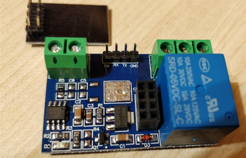
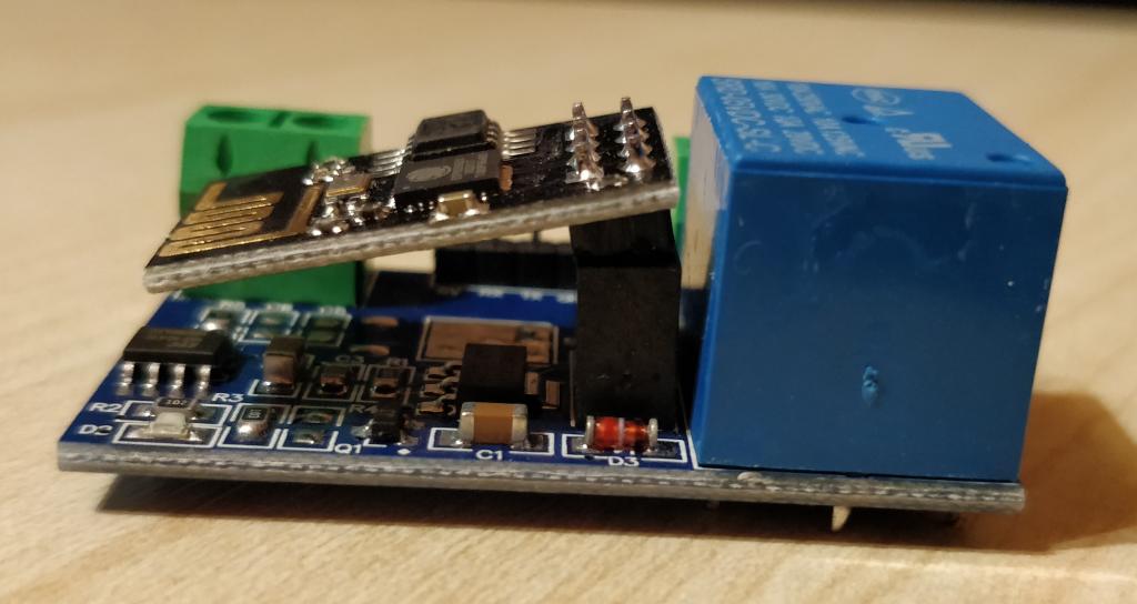
There are actually 2 basic designs floating around on Aliexpress. The one that I’m talking about here is where esp8266 module plugs into the mainboard through 8 pin connector like this:
The other one integrates esp8266 on the relay board directly.
From the shipping perspective this modular design is a bit unfortunate since cheap/free shipping from Aliexpress will usually arrive in normal soft envelopes that just have 1 layer of bubble wrap as a padding.
As a result all 3 boards that I ordered arrived looking like this:
Nevertheless they actually worked fine. I was probably just lucky though and I kind of like modular things more in principle.
Interesting thing about this modular design though is that the relay is actually controlled by the STC 15f104W MCU on the main board which is programmed to turn the relay on when it sees “\xa0\x01\x01\xa2” on its UART port and off when it sees “\xa0\x01\x00\xa1“.
That UART is accessible either through the 4 PINs between the screw terminals or input from the esp8266. So you can actually run it without the esp8266 and control the relay directly over UART PINs or even reprogram the 15f104w.
ESP8266 board comes flashed with esp8266 AT firmware which allows esp8266 to be controlled using AT commands on the serial port.
By default the module comes in AP mode which means that it will show up as an Wifi access point that you can connect to. I wasn’t really interested in that so I reconfigured it to connect as a client to my main wifi network.
To reconfigure ESP8266 you have to connect UART over the 4 pins between the screw terminals using an USB to UART TTL cable like this:
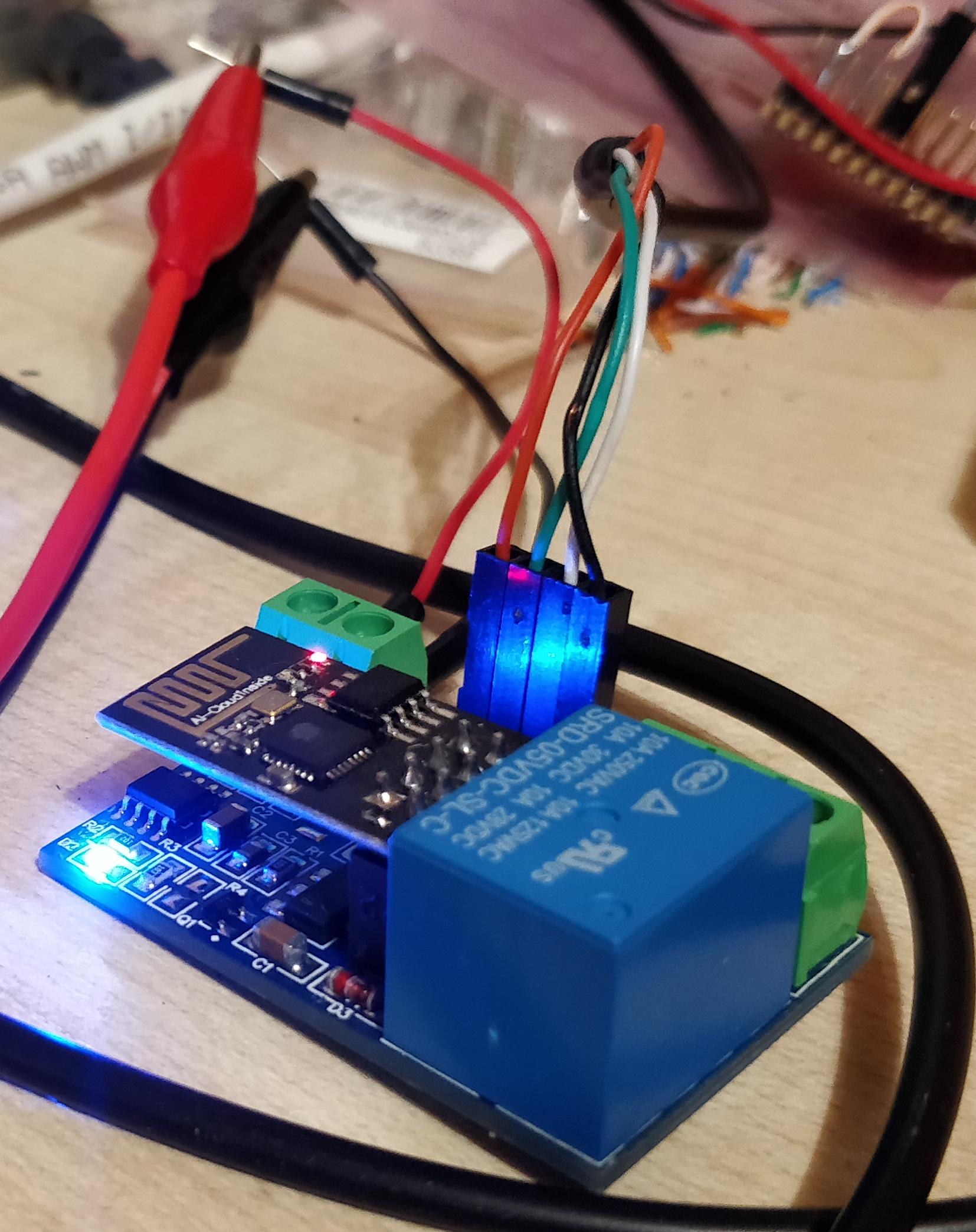
I just happened to have the 5V power supply also connected but it’s not really required at this step, just for reconfiguring power from USB should be enough.
This can be done like this:
$picocom -b 115200 --omap crcrlf /dev/ttyUSB5 AT+CWMODE=1 AT+RST, AT+CWJAP="myssid","mypasswd" AT+CIPMUX=1 AT+CIPSERVER=1,8080 AT+CIFSR AT+IPR=9600 |
After this, communications will switch from 115200 to 9600 baud so you will lose the link and would need to switch picocom to 9600 baud to do anything further. But anything else isn’t really required anyway for our simple use case, so just disconnect picocom with CTRL+A CTRL+X.
AT+CIFSR command should have printed out what is the IP of the module. In my case it looked like this:
AT+CIFSR +CIFSR:STAIP,"192.168.17.40" +CIFSR:STAMAC,"2c:3a:e8:4f:30:02" OK |
Now you can just create a TCP connection to that IP at port 8080 and send the relay commands that I mentioned before. ESP8266 will pass these to the STC 15f104W MCU which in turn will control the relay.
As an example here’s a trivial python script that will connect to the relay and turn the relay on and off in an endless loop in 4s intervals:
import sys import time import socket IP = "192.168.17.40" PORT = 8080 RELAY_OPEN_CMD = "\xa0\x01\x01\xa2" RELAY_CLOSE_CMD = "\xa0\x01\x00\xa1" SLEEP_S = 4 s = socket.socket(socket.AF_INET, socket.SOCK_STREAM) s.connect((IP, PORT)) while 1: s.send(RELAY_OPEN_CMD) time.sleep(SLEEP_S) s.send(RELAY_CLOSE_CMD) time.sleep(SLEEP_S) |
And here’s how the result looks like: