Let’s assume you somehow came into possession of a Raspberry Pi (rpi) 4 and want to configure it for something useful.
After writing the raspbian image you discover though that you have no suitable cables nor converters for the micro HDMI port.
If you do have a USB to serial TTL converter though, you can just configure rpi over the serial port.
In order to do that we first have to enable the first serial port on the rpi. To do that you have to mount the micro SD card with the raspbian image on your computer and add these lines to enable the serial console to config.txt:
… where you have to replace sdz with actual device name of your SD card (you can find it from the output of dmesg for example).
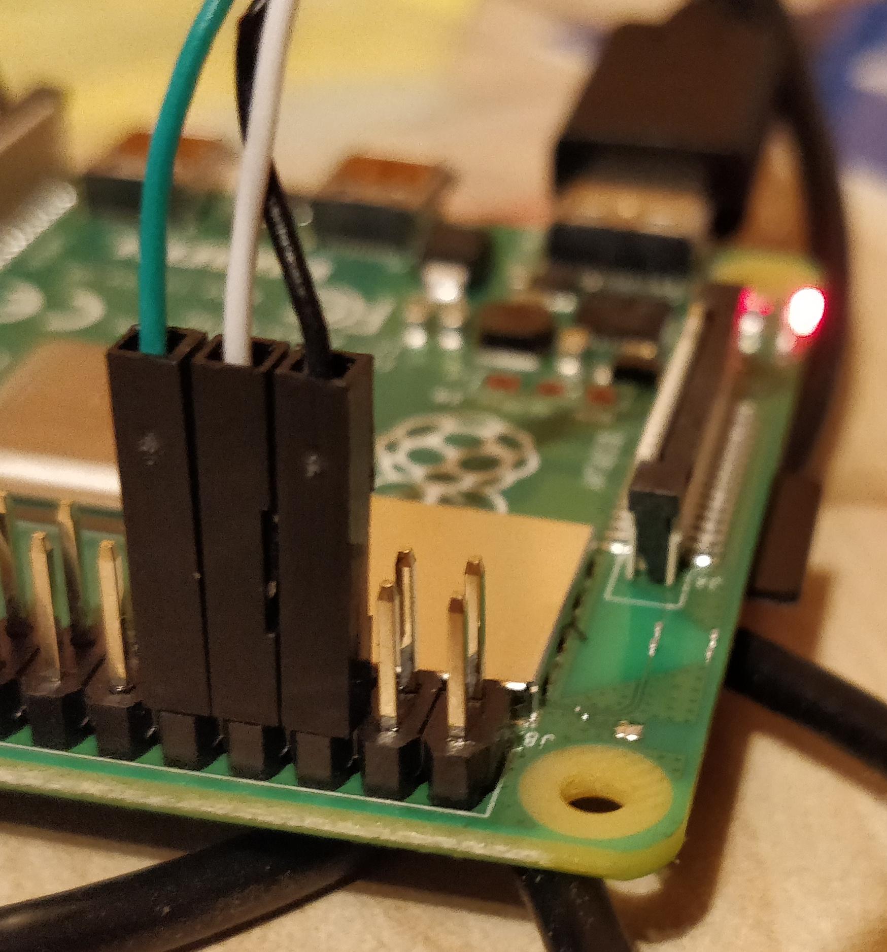
Now connect the USB to serial cable like this:
ground -> pin 6 (GND)
rx -> pin 8 (TXD1)
tx -> pin 10 (RXD1)
+5V will remain unconnected
… which looks something like this:
You should be able to access the terminal using something like this:
picocom -b 115200 /dev/ttyUSB5
Where you have to replace ttyUSB5 with whatever device for the USB to serial converter on your system (which you can again find out from the output of dmesg).
One of my hobbies is building robots. The largest one to date is this (me for scale):
I created it as a general large platform for outdoor experimentation that would be able to take on various practical tasks in a more or less autonomous manner.
What I didn’t anticipate is how hard it is to build such a platform in a way that is both economical and reliable.
While it does work in general, the Mean Time Between Failure has proven to be somewhere in the range of an hour or so.
When something major breaks, the robot goes back to the parking lot waiting for the next season while I contemplate if I want to spend more resources on fixing it. So the progress on this project has been rather slow to put it mildly…
Anyway the first idea was to use it as an autonomous lawnmower. I did get around to doing some mowing experiments with a single blade as you can see in this video:
As you can see the mowing part works, but it isn’t particularly impressive. Adding the second cutting motor would have helped a bit as would using a single large blade with a more powerful motor like the one that is used in commercial cordless mowers like Makita DLM380.
But in general this chassis seemed just too powerful and dangerous for an autonomous mowing operation in the garden. Nowadays Ardumower seems like a much better base for autonomous mower projects.
Personally I also lost interest in the specific problem of mowing several years ago since it isn’t a personal itch anymore — I have sheep nowadays to keep the grass at a reasonable height.
So anyway I decided to repurpose the robot for watering plants in the field.
It’s something that I potentially actually need, requires quite a bit of carrying capacity and the work happens out in the field where it can’t cause that serious damage when it goes out of control. It also tried the job of the sheepdog for a while 😛
Motors
The motors that I use are really old 24V wheelchair motors. These motors seemed a really good fit for my purpose because of the high torque and generally robust construction.
They are really hard to source though at a reasonable price (new ones go for min. 400+EUR/pair) and it’s hard to connect these to any wheels that are cheap and fit for agricultural purposes.
I managed to find a local wheelchair repairman who sold a pair of these for 25EUR but the downside is that these are old used ones are rather one-off and in unknown condition. You are lucky to get a matched pair and mine had an obscure shaft with a keyslot. If one motor fails you will probably have to find another pair which likely has a bit different dimensions, shaft length, -diameter and type which would require a bit of redesign.
The spiral spring holding one of the brushes in place on one of the motors rusted through. Finding a suitable replacement spiral brush spring seemed rather hopeless so I patched it with a random spring of completely different type. It kind of works but is somewhat unreliable — it sometimes loses contact and needs a tap on the back.
During the last couple of years brushless hub motors have been coming down in price and I think nowadays I would go with these instead. Finding ones that are wide enough with at least 14.5″ diam and shipping price that wouldn’t be half the price is still a challenge though.
Wheels
I decided to use wheelbarrow wheels since there’s a wide selection available, there are rather wide ones with a large diameter that are suitable for rugged terrain and they are cheap.
Attaching these to the shaft is tricky though, since wheelbarrow wheels are generally built with the idea that you put a rod through them which rests on a bearing.
I decided to use an industrial taped bore and just drill matching holes through the wheelbarrow wheel rim. The best rim that I found was a bit conical though, which made it almost impossible to perfectly center the taper bore on it.
To attach it to the wheelbarrow wheels I had to find a shaft key, taperlock bush for that particular shaft and key size and a fitting taper bore.
These I had to order from different suppliers from the other side of the world which took quite a while. I didn’t actually find perfectly matching ones so I had to hammer and file it a bit and you can see on the picture that the taperlock bush has actually cracked:
Looking back at the effort spent, ordering a special made one from some local metalworks company would probably have been easier and maybe even cheaper.
The battery
The first generation used two Exide ES650 lead-acid deep cycle gel batteries in series. One of these failed though a bit after the end of the warranty. I only managed to use it for a couple of hours in total over these two years because chassis-motors-wheels took unexpectedly long to complete.
That battery failed after I used it to start a car with a dead battery once, which is kind of strange.
While deep cycle batteries aren’t certainly meant for that, I don’t think getting it damaged with using it for starting once is the expected result.
Anyway, having lost one battery I had a choice of either buying a new one for the pair or switching to some other battery chemistry completely.
While still having one usable battery would have made replacing just the other somewhat simpler and certainly cheaper proposition in the near term. In the long term this looked like a dead end though.
These batteries seem to have an expected lifetime of around 5 years and the functioning one was approaching that even though it has seen barely any actual use.
Also the energy density is obviously a lot lower than for many more modern chemistries.
I didn’t like to go with Li-Ion batteries based around 18650 cells that are otherwise rather popular with DIYers, since reading the forums of the communities shows just how fickle these can be and how much attention to the detail is needed.
Treating these batteries in just the right way for them to last more than a thousand or so cycles seems to be a science in itself and there’s a chance of them bursting to flames if you do something wrong.
I contemplated LiFePo batteries which are safer and should last a bit longer (~2-3k cycles) but then I found LTO cells (Lithium titanate) cells instead.
Lithium-Titanate cells seem to be so much better for my use for many reasons:
around 30k cycles or around 30 years of lifetime. I didn’t want to face losing the battery again before starting to seriously use it.
safe to handle. It seems right next to impossible to get them to burn with puncturing, cutting, overcharging etc. You can see how much abuse they can take here.
you can charge them fully in 10 minutes and discharge at 10C (400A in my case)
cold temperatures do not reduce performance nearly as much as they do for li-ion for example. Actually these are rated for operating down to -50C. I might want to drive the robot during the winter too and when the battery is not in use with the robot it will be used for energy storage system at the birdhouse where we have outdoor temperatures.
over draining or over charging these isn’t as much of a problem as with other Li battery chemistries. You can just pretty much use Lead-acid charger even without BMS if you do not care about getting 100% of capacity out of it. I guess you might also lose some of the theoretical lifetime that way but having such a nice direct lead-acid replacement might be worth it.
There are also downsides of course. Specific energy of the LTO pack is a lot lower than it would be with some other Li chemistries like NMC (73Wh/kg vs. 200Wh/kg) and the price is a bit higher (around 20% for the specific setups that I compared).
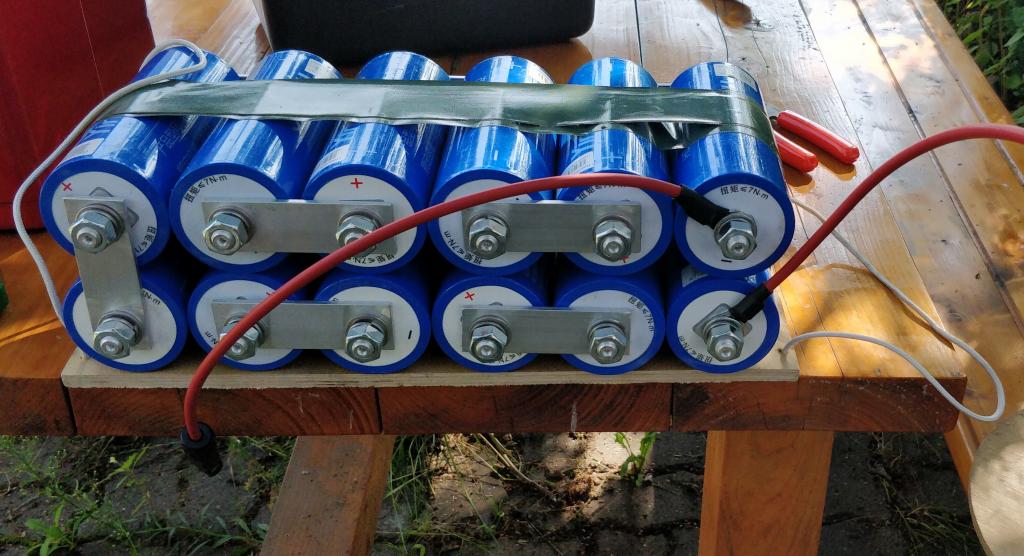
So anyway here’s the LTO battery pack I ended up building:
My pack consists of 12 * Yinlong 40Ah 26650 cells. The nominal voltage of these cells is 2.3V so for the pack it is 27.6V.
The busbars connecting the cells are cut from 4mm thick aluminium bar. I contemplated getting a copper bar for that but it’s harder to find and besides the threaded connectors on the cells are made of aluminium anyway.
Controller
I use Sabretooth 2x25A driver. This has worked flawlessly and has taken some serious abuse without any complaints. For example one year I forgot to remove it from the robot for the winter and I discovered it in the spring. Water had somehow gotten into the controller box and the board was frozen in ice.
Just melted it and dried… has worked without any problems.
Back in 2014 I wrote a post on RTK-GPS using Navspark NS-RAW boards. Back then I promised to write a follow-up once I have done some testing. I didn’t quite think it would take so long but the reason behind the delay is that I never quite got it working as well as I expected and tried various things over the years which took time, and I lost interest couple of times in between.
A couple of people have asked me how it worked, so finally I decided that enough is enough and I’ll just describe how far I got.
TLDR version: NS-RAW in seems to perform significantly worse than the u-blox of the same era. Even if it had performed at a similar level, single frequency GNSS in general just seems to be unsuitable for reliable ground based robot navigation. It might work at some times of the day where the satellite visibility and geometry happens to be just right and you are testing in a large open field, have good antennas etc. but for most realistic cases it will not be reliably usable.
Setup
Navspark has this to say about the required conditions to be met for a stable RTK FIX:
NS-HP or NS-HP-GL are single frequency RTK receivers. For reliable consistent single-frequency RTK operation, they require 12 or more usable satellite signals above 15 degree elevation angle with SNR no less than 38dB/Hz.
NS-RAW is single-constellation so I’m limited to only GPS. Looking at the GNSS radar tells me 5-9 GPS satellites would be visible from my location at different times of the day (with 15 degree elevation). So 12 satellites would be impossible here. Other sources say that you need 7 satellites min. to get a RTK FIX solution (and min. 5 to hold it). That would have been a bit more realistic requirement, and besides, an earlier u-blox LEA-6T test got a FIX solution just fine so I decided to go on with the test.
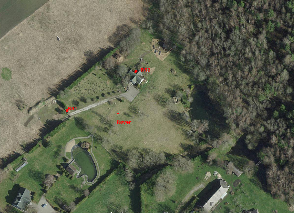
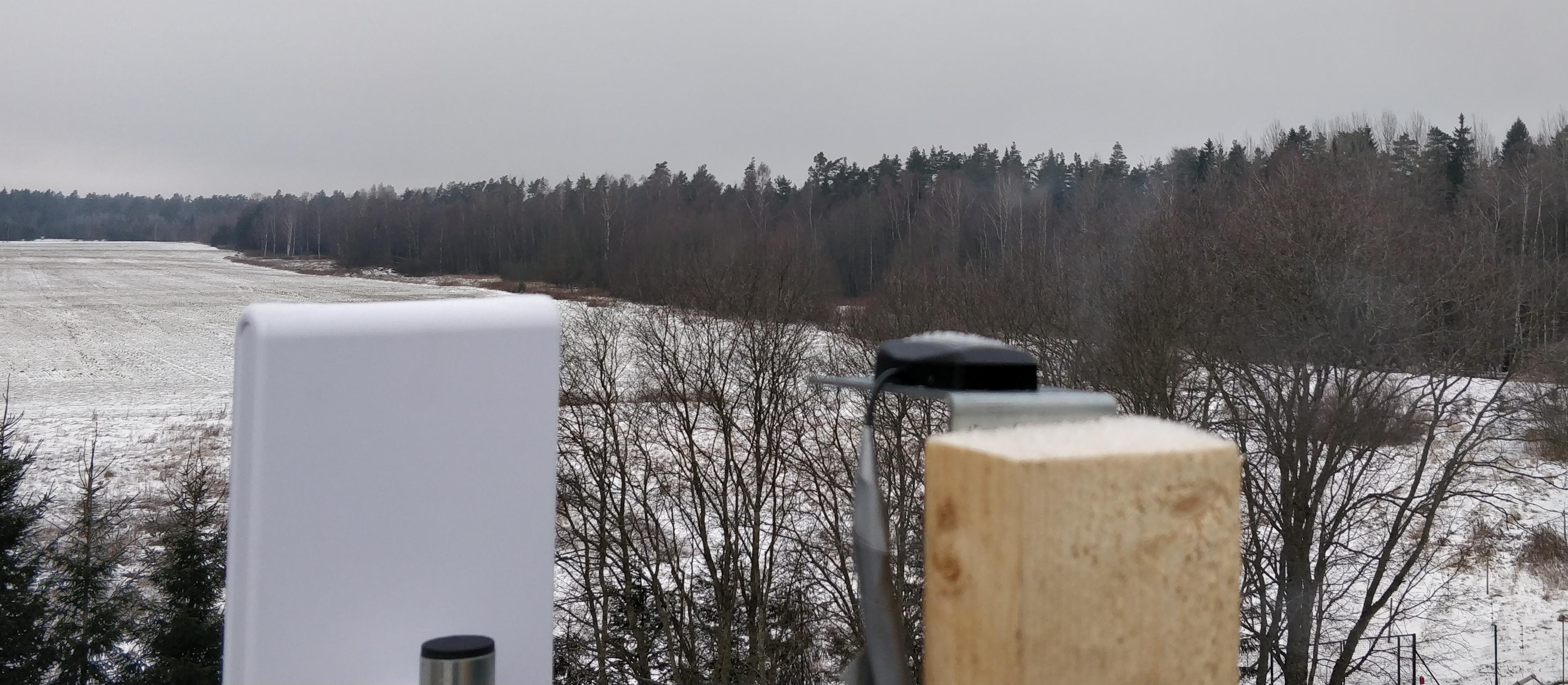
Here’s what my test ground looks like:
The plot has 20m high forest in the N & NE directions. Other sides have better visibility but all the sides have at least one row of 20-30m trees + some sporadic buildings and trees all over the place.
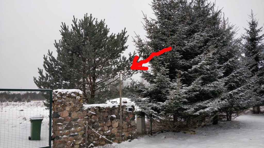
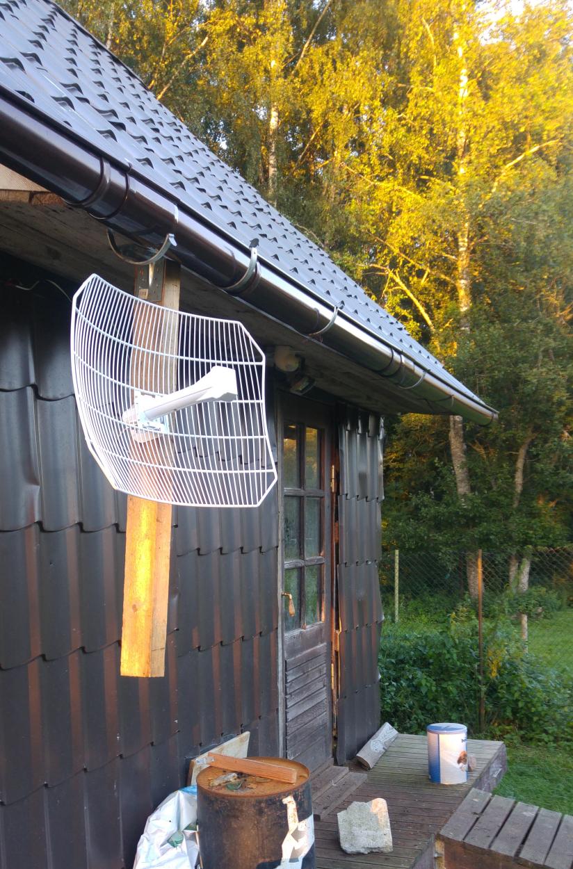
BS1 is the original base station that was described in the previous post on the topic. It uses Satmar FME marine active GPS antenna. I have added a 15cm wide ground plane below it (a paint can lid). The location of BS1 is somewhat unfortunate since it is basically surrounded by some trees from all the sides. When I originally chose the location for the base station I didn’t have good access to the roof of the main building so I chose a spot that was furthest away from the house, so that it wouldn’t block satellites from that side. Here’s the picture of the location:
BS2 is the new base station at the top of the roof. It’s about 8m higher than BS1 and hence has better satellite visibility. Tri-Band GPS/Galileo, Beidou, GLONASS Active Antenna is used. It looks like this:
“Rover” is me walking around with a laptop and NS-RAW with an antenna setup identical to BS1.
Everything is connected over WIFI.
Best case – localization between two base stations
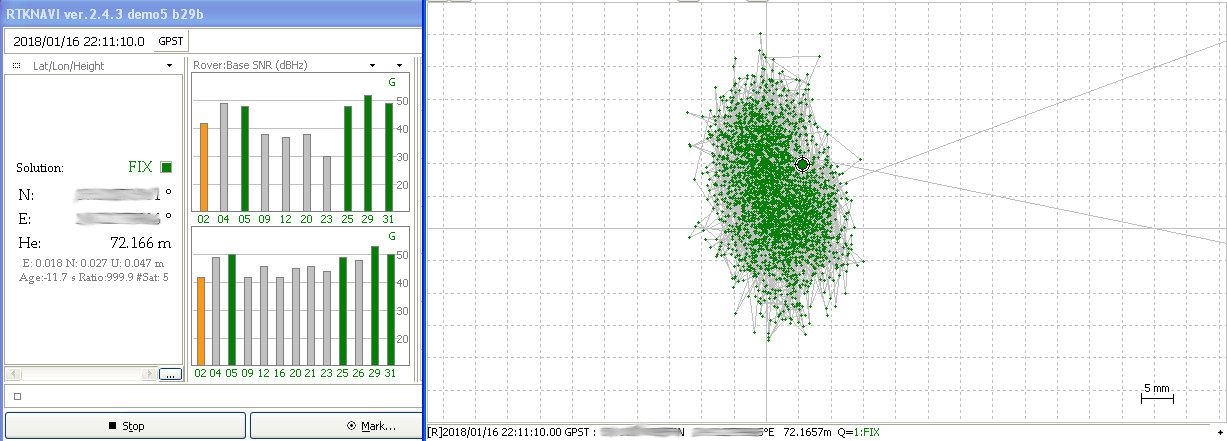
Using BS2 as base station and BS1 as rover in the Kinetic mode should give us a good idea of what is the best that can be achieved with this hardware on my plot. Even though BS2 doesn’t have good sky visibility it’s better than a real rover will ever have since it’s located on a pole that is a couple of meters higher than the rover will ever be, and has less sky blocked by the house than a rover normally would.
I finally got RTK working rather well in this scenario and it has FIX most of the time. The location stays in a ~5 cm^2 area for the 8h session:
I was cheating a bit though – for localizing static points I use Integer Ambiquity Res mode FIX and hold. This mode takes past measurements more into account when calculating the current location than Instantaneous or Continuous would, which makes position mode stable but would also make it return the wrong position for longer if the rover was actually moving. I also used demo5 ver. of RTKLIB by rtklibexplorer which got more FIX solutions than the mainline RTKLIB.
Driveway test
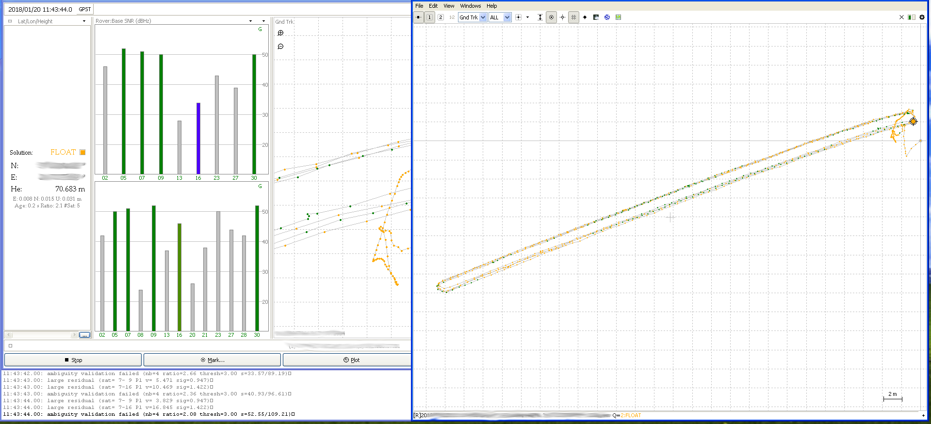
Next I walked up and down the driveway as a rover a couple of times to see if I can get comparable results to my u-blox test at the same location in 2013.
There were lots of slips, large residuals and ambiguity validation failures in the RTKLIB logs. Most of these errors are said to be commonly caused by not having clear enough view of the sky and the consequent multipath errors.
This seem likely since the rover certainly didn’t have a great view of the sky from 2 sides and things seemed to get worse with stronger winds (when trees had leaves and these were moving a lot).
With that said, the driveway basically has the best visibility in my yard that a real rover could ever have, so this is the most optimistic-realistic scenario. Even though the common satellite count is really low and we seem to be in FLOAT mode half of the time, the points are reasonably close (~20-30cm) and it would be usable for real navigation if this precision were repeatable 24/7 all year round. This test was done in January so no leaves on the trees which probably reduced errors a bit and made it even more of a best-case scenario.
Rover circle
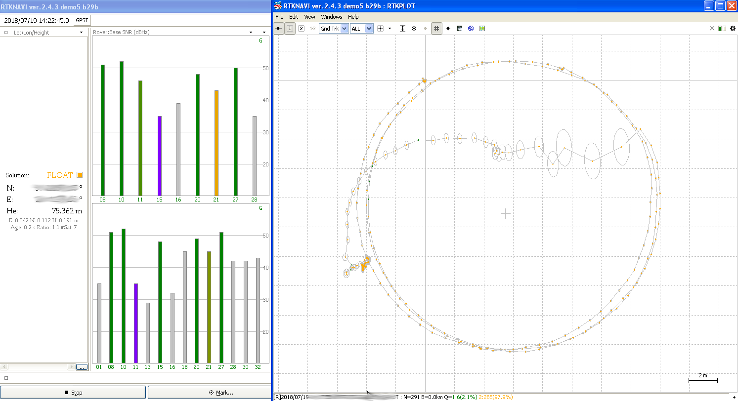
Now for a more realistic test – walking in a circle with 20m diameter in the middle of the yard in mid-summer when trees have leaves.
This looks rather bad, only 2.1% of the points have FIX solution. The FLOAT solution was reasonably precise for 3 circles and then suddenly wandered through the circle. We see that most of these points have a lower confidence than FLOAT points on the actual circle so we could filter those out on that basis, but we also see a single FIX solution point in that path which is a couple of meters away from the actual location.
This test was done with integer ambiquity res. set to continuous.
What next?
I have put the navigation project on hold for now. I expect L5 capable chips to be much more common in the next 2 years which along with new Galileo satellite launches should considerably improve the precision of navigation at my location (NE Europe). L5 should be much less prone to multipath problems that seemed one of the main things throwing my rover signal off. Broadcom 47755 is the first mass consumer L1/L5 chip and others will surely follow.
Finally here’s a list of relatively cheap alternatives to NS-RAW that are available right now and would be rather interesting to try in similar situation but not interesting enough for me to actually buy the test hardware:
My original tests in 2013 seemed to get much better results with LEA-6T so u-blox LEA-8T that is available for ~75$ per module might give better results. You would also be able to try out various hacks and configuration tweaks described in the awesome rtklibexplorer blog.
Navspark NS-HP series (NS-HP-GL, NS-HP-BD) might also give somewhat better results than NS-RAW since these have multi-constellation support. Having the ability to use Glonass satellites in addition to GPS would almost double the average number of visible satellites in my location. These chips also do RTK on board so you don’t have to have a separate computer for running RTKLIB which will save you both weight and power. They also claim significant improvements in environments like mine in the newer firmware versions.
u-blox M8P based boards might also be interesting, these are multi constellation (GPS, BD, Glonass) L1 chips that do RTK calculations on board so you only have to provide a communication link. Such boards are for example Tiny RTK from Drotek (~215€) or the one from CSG (~239€).
Drone operators seem to like Emlid Reach. Under the hood it’s a combo of u-blox M8T + Intel Edison for processing and RTKLIB with much friendlier frontends than bare RTKLIB has. It seems that some of their customers are happy with the results and others seem to almost never geta FIX solution.
After having read lots of forums of users trying to use these cheap single frequency RTK solutions, my conclusion so far is that it seems to require intimate knowledge of almost endless GNSS related stuff, a very good sky visibility, living in a place where satellite geometry is just right for large part of the time, good antennas and specific weather conditions. In short it doesn’t seem to be feasible for generic rover navigation that requires constant precision in the dm range in all corners of the yard.
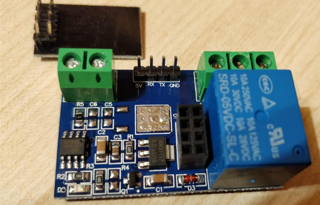
Just some quick notes on using 5V esp8266 relay module. Manufacturers page seems to be this even though terminal and pin positioning on the pictures is a bit different.
For just ~2.4€ it will give you the ability to switch electrical loads over Wi-Fi 🙂
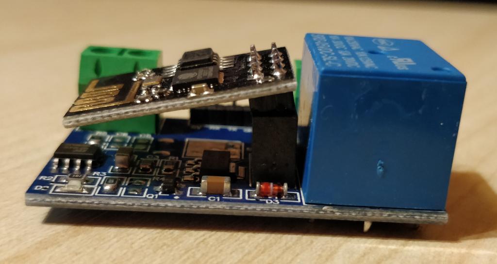
There are actually 2 basic designs floating around on Aliexpress. The one that I’m talking about here is where esp8266 module plugs into the mainboard through 8 pin connector like this:
The other one integrates esp8266 on the relay board directly.
From the shipping perspective this modular design is a bit unfortunate since cheap/free shipping from Aliexpress will usually arrive in normal soft envelopes that just have 1 layer of bubble wrap as a padding.
As a result all 3 boards that I ordered arrived looking like this:
Nevertheless they actually worked fine. I was probably just lucky though and I kind of like modular things more in principle.
Interesting thing about this modular design though is that the relay is actually controlled by the STC 15f104W MCU on the main board which is programmed to turn the relay on when it sees “\xa0\x01\x01\xa2” on its UART port and off when it sees “\xa0\x01\x00\xa1“.
That UART is accessible either through the 4 PINs between the screw terminals or input from the esp8266. So you can actually run it without the esp8266 and control the relay directly over UART PINs or even reprogram the 15f104w.
ESP8266 board comes flashed with esp8266 AT firmware which allows esp8266 to be controlled using AT commands on the serial port.
By default the module comes in AP mode which means that it will show up as an Wifi access point that you can connect to. I wasn’t really interested in that so I reconfigured it to connect as a client to my main wifi network.
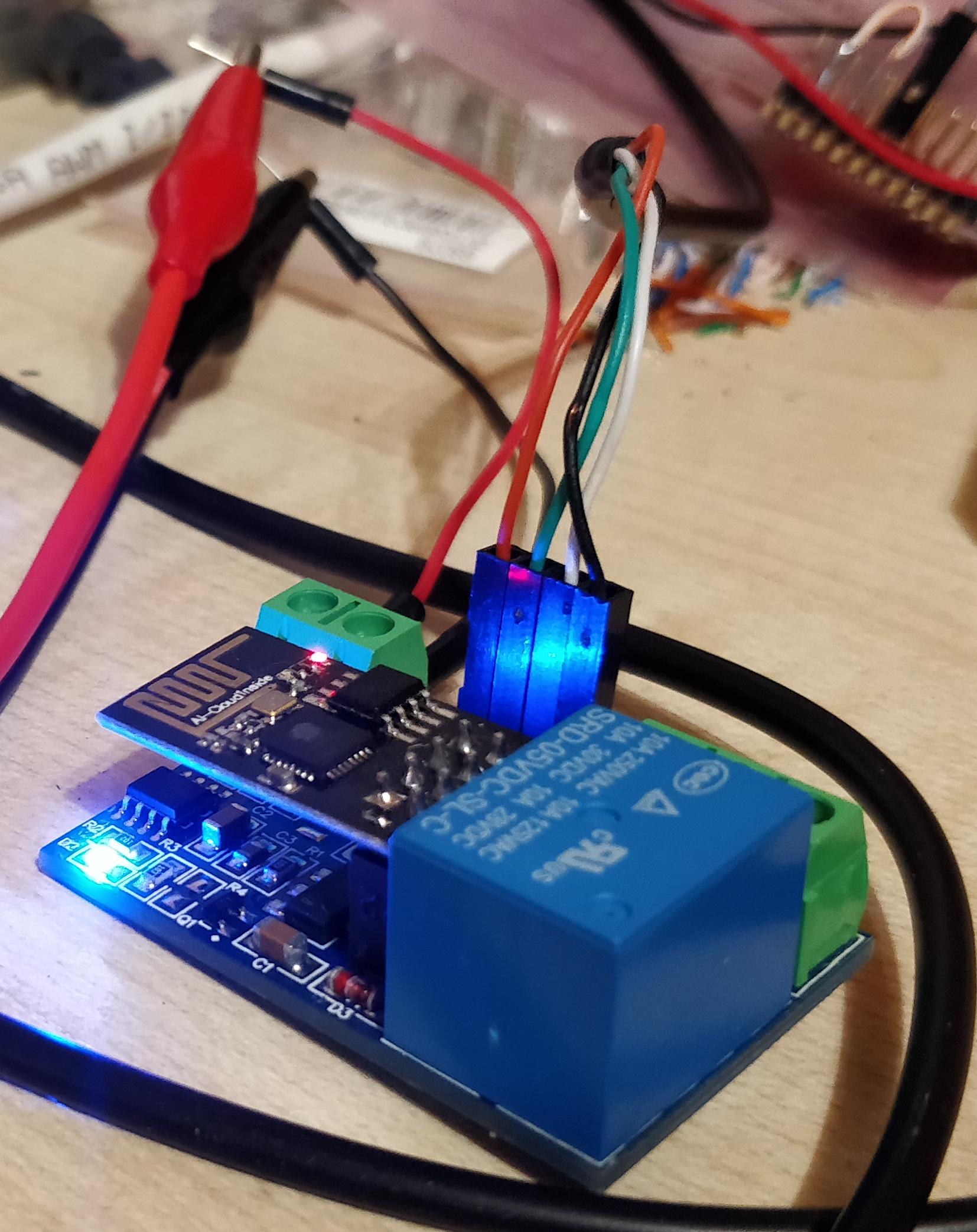
To reconfigure ESP8266 you have to connect UART over the 4 pins between the screw terminals using an USB to UART TTL cable like this:
I just happened to have the 5V power supply also connected but it’s not really required at this step, just for reconfiguring power from USB should be enough.
After this, communications will switch from 115200 to 9600 baud so you will lose the link and would need to switch picocom to 9600 baud to do anything further. But anything else isn’t really required anyway for our simple use case, so just disconnect picocom with CTRL+A CTRL+X.
AT+CIFSR command should have printed out what is the IP of the module. In my case it looked like this:
AT+CIFSR
+CIFSR:STAIP,"192.168.17.40"
+CIFSR:STAMAC,"2c:3a:e8:4f:30:02"

OK
Now you can just create a TCP connection to that IP at port 8080 and send the relay commands that I mentioned before. ESP8266 will pass these to the STC 15f104W MCU which in turn will control the relay.
As an example here’s a trivial python script that will connect to the relay and turn the relay on and off in an endless loop in 4s intervals:
importsysimporttimeimportsocket
IP ="192.168.17.40"
PORT =8080
RELAY_OPEN_CMD ="\xa0\x01\x01\xa2"
RELAY_CLOSE_CMD ="\xa0\x01\x00\xa1"
SLEEP_S =4
s =socket.socket(socket.AF_INET,socket.SOCK_STREAM)
s.connect((IP, PORT))while1:
s.send(RELAY_OPEN_CMD)time.sleep(SLEEP_S)
s.send(RELAY_CLOSE_CMD)time.sleep(SLEEP_S)
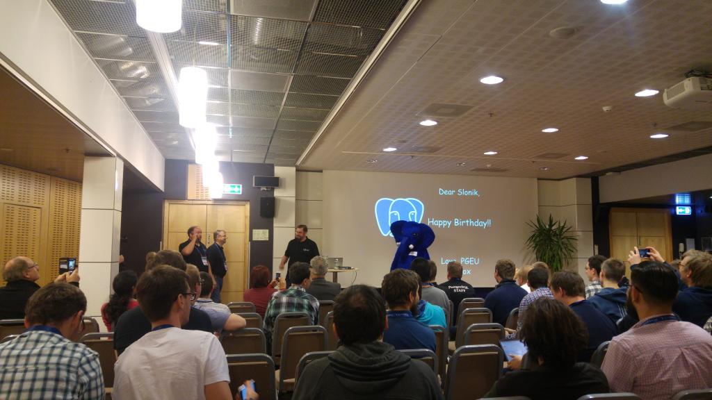
Since this year’s European PostgreSQL conference pgconf.eu happened to take place in my home country I just couldn’t pass the opportunity to go.
I’m not really a huge PostgreSQL user though — I mostly use it for personal projects, but have also done at least one rather unconventional proof-of-concept project on it at work (a largeish graph DB).
At work the main production databases that I’m currently responsible for (or have been in the past) are all based on MySQL/MariaDB, but this is mainly because these decisions were made 10+ years ago when the pros and cons of each choices were quite different than they are today. It’s rather likely that for all the new projects I would rather use PostgreSQL.
I won’t go over the talks one by one but rather share some general themes that I noticed.
Zeitgeist
There’s a German word Zeitgeist which loosely means the spirit of the time. I have begun to notice that at conferences there’s often some unifying subtopic of the project that is somewhat unproportionally important to the particular community at that time for some reason. For example at Europython 2010 the zeitgeist was all about concurrency and ways to get around the GIL. At Europython 2015 I barely heard anything about concurrency anymore, even though things at that front haven’t changed much in between — instead everyone was focused on data mining and scientific computing. So anyway I feel that at pgconf 2016 the central topic was replication. There were many talks exploring different approaches to replication and various master-slave switchover orchestration tools. It will be interesting to see what solution the community will settle on in the next couple of years.
Popularity
PostgreSQL has been gaining a lot of popularity over the recent years, probably mainly because of the uncertainty related to MySQL after Oracle bought it. This also means that many commercial companies see opportunities in selling support/consultancy around postgres related things. In general for-profit companies tend to be interested in having something to differentiate themselves from the competition so they are somewhat inherently motivated to create custom extensions and solutions instead of working together. It certainly felt at the times that each company at the conference had a different solution for handling replication and cluster orchestration each with its own up- and downsides. Let’s just hope it doesn’t end with a full scale Unix wars scenario. PostgreSQL has always had a rather rich landscape of forks so maybe they have already learned to handle this somehow.
Where to do the complex stuff?
There were several talks about some of the more powerful constructs and capabilities of PostgreSQL from window functions, recursive CTEs, lateral joins, upserts, aggregate filters to various nosql capabilities, custom datatypes, foreign tables, operator overloading and support for countless programming languages.
Which brings us to a rather classical dilemma: should we use various powerful tools that the DB provides and be tied down to it as a result, or use the DB as a simple datastore and do the complex stuff in the app? I see it as a continuum where on one end you only use simple queries (probably through ORM) and on the other end you have monstrosities like Oracle APEX where even the application itself is in the DB.
The keynote speaker from Adyen said that he believes that the decision to avoid procedures, triggers etc. was the best tech decision they did even though it was for completely different reasons. My experience is more or less the same – I think a good rule of thumb is to avoid non-declarative features but be rather liberal with everything else.
Case studies
For me the most interesting talks at the conference were various talks about real system setups and problems encountered along the way. There were several of these types of talks, starting with the keynote delivered by Michiel Toneman from Adyen which is a quickly growing payment processing company currently serving ~60 billion payments per year. They have been undergoing exponential growth for years which has led to some rather interesting scaling problems. Their master database is currently over 40TB and has 11 tables with a size over 1TB. Their largest table is currently around 11TB. Michiel talked about the reasoning and complexities around choosing PostgreSQL for a payment processing company, which is in a field usually dominated by high cost proprietary databases like Oracle and Sybase. It was interesting that postgres usage at Skype had been kind of a validation that probably made it a acceptable choice elsewhere.
Another interesting talk was about problems that Skype has encountered with PostgreSQL. The interesting part for me was that even though we use MySQL we still have encountered most of the same problems. That’s because many of these problems were just something that you encounter when running DB under serious load (lock queues, small degradations in IO performance having snowball effects, lagging read replicas, cleaning up bloat etc.)
For the last month or so me and my partner have taken cold showers in the morning. There are seemingly endless lists of benefits of this available on the Internet so I won’t bore you with another one. For me the main goals were to boost the immune system and to really wake up, both of which it really seems to provide.
It’s also a good exercise of willpower.
We have also extended our open water swimming period. Here’s a nice picture from today of the local bog lake (Kõnnu järv).
The air was at 15 degrees C and the water probably somewhere around 7 degrees C. After going in, there was this burning cold feeling but it’s kind of enjoyable in its own strange way. After coming out the air actually feels rather warm and there’s this strange heating feeling under the skin all over the body long afterwards.
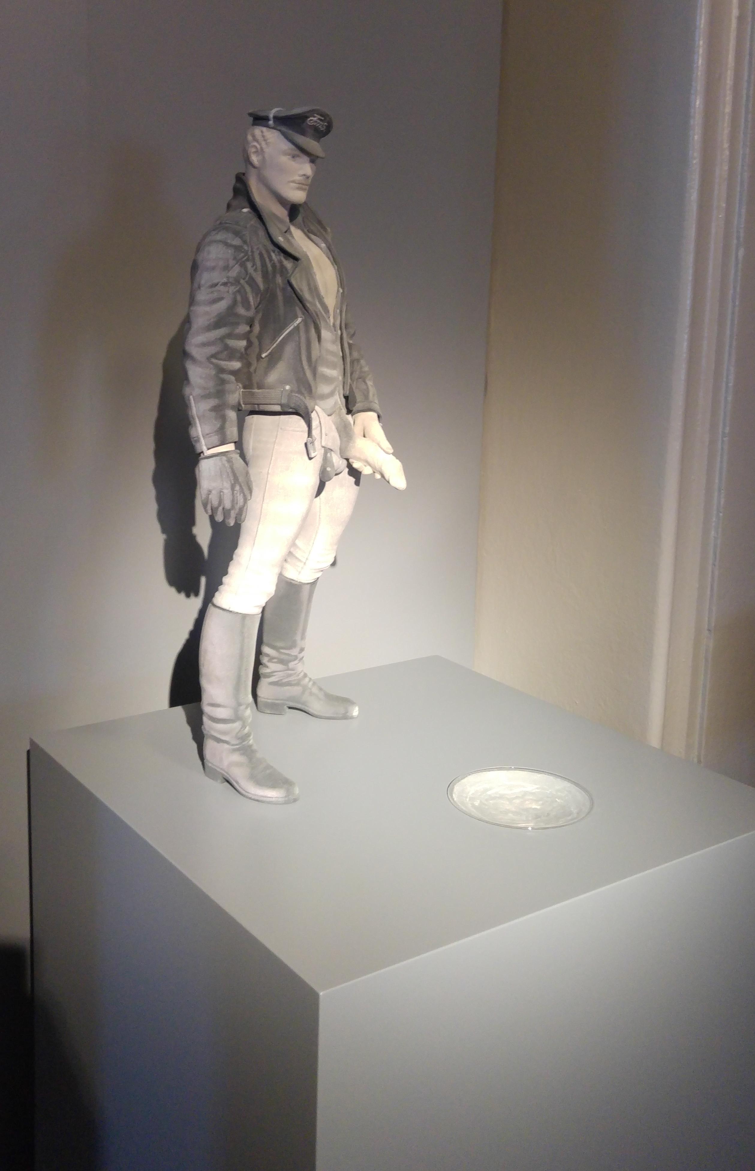
In addition to many Tom’s works there’s also this Tom-inspired 3D printed drinking fountain in the lobby:
It wasn’t usable for its intended purpose for some reason but is still one of the best real uses of 3D printing I have seen so far.
There was also this drawing of a duck by Tom from his youth. As a duck keeper I have to say Tom’s tendency to exaggerate the sizes of certain body parts is indeed clearly visible.
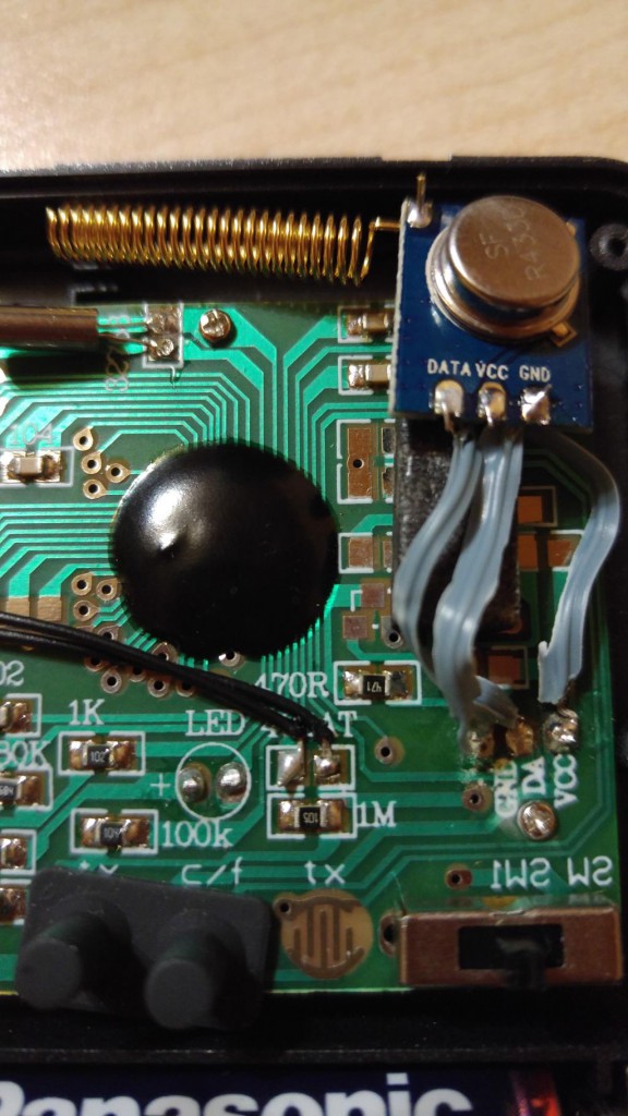
As mentioned in my last post about cheap Chinese wireless temperature/humidity sensors, one of the three devices that I ordered was broken. It did show correct values on the local screen but no messages were seen over the radio link.
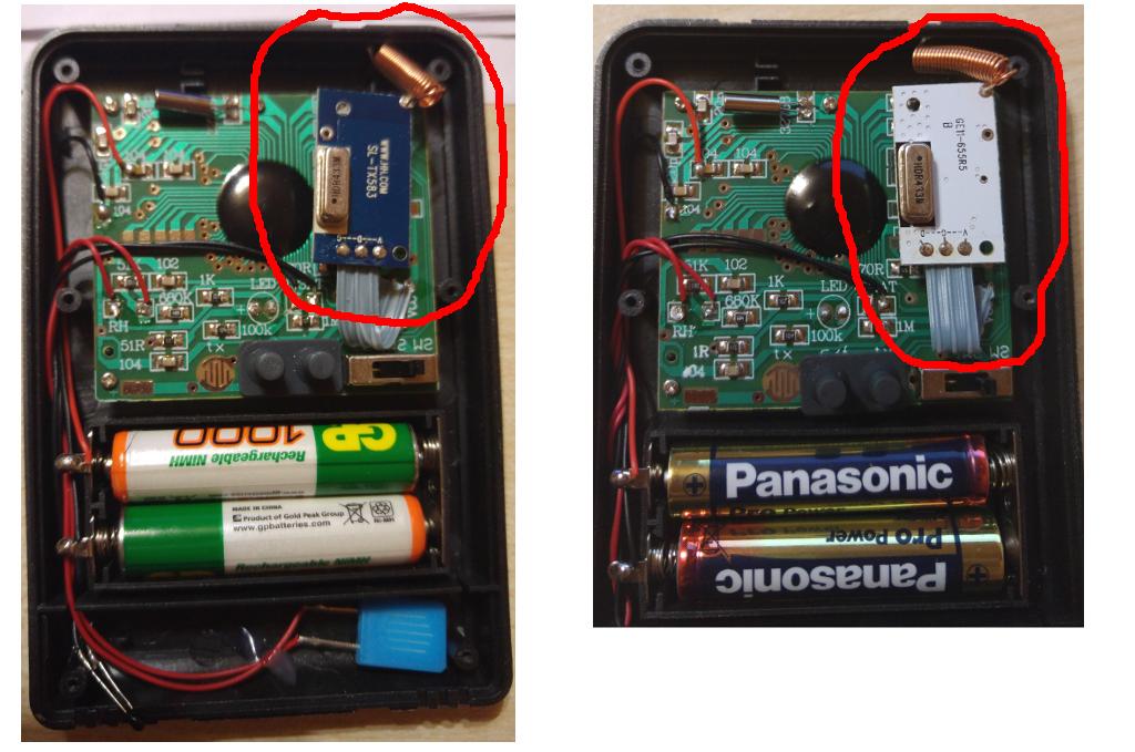
I decided to open it up to see if there’s anything obviously wrong inside. Here’s how the internals looked like:
The 2 working sensors both had the blue radio module shown on the left and the non-working sensor had the white module shown on the right. Since I had RTL-SDR I decided to see if the broken module sends out any signal at all. I found a very detailed blog post describing the steps for doing it.
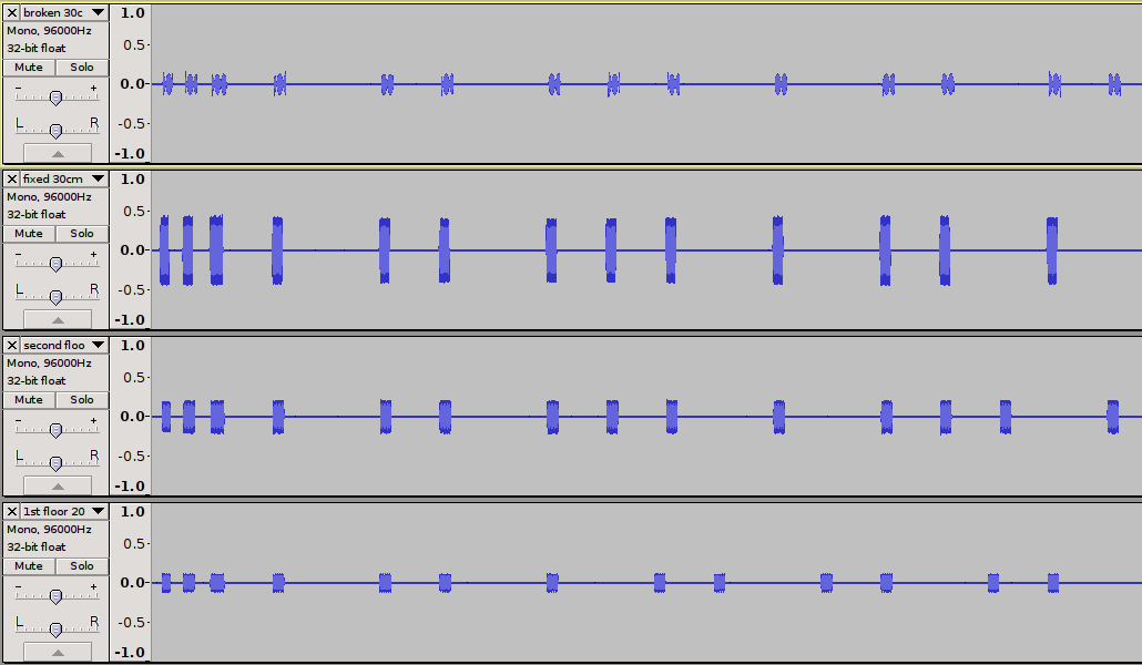
Here’s what my signals looked like:
The topmost signal is from the broken radio module as measured ~30cm from the antenna. The next one is the signal from the replacement radio module from the same distance and the last 2 signals are from the two other sensors which were located much further from the antenna.
As we can see the broken signal is rather unstable and can’t hold stable high.
It looks even more interesting when zoomed in:
Here’s how the sensor looks with the replacement radio module:
The fixed sensor works rather well, the signal is clear from ~20m away through 2 concrete floors.
I was kind of missing the fun temperature charts that I had at my previous home so I decided to get some sensors for the new house too. Using 1-wire network like I did previously didn’t seem reasonable this time around since my current house has 3 floors and cabling it in a way that wouldn’t be ugly would have taken too much effort.
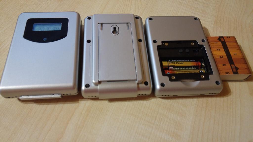
So instead I decided to find some cheap wireless temperature sensors. It turns out you can get a reasonably looking temperature+humidity sensor with a local display and 433 Mhz radio for just 7€ a piece (with free shipping). You can also buy these sensors in a cheap kit with a central screen that shows values from all the senors plus some additional stuff like clock and sunrise times.
I wasn’t really interested in the central screen, so I just bought 3 sensors.
These sensors display humidity and temperature values on the screen and send out these measurements once a minute. When the sensor sends the message it blinks the red led in the front panel which might be a bit annoying if you place it somewhere where you can see it at night. I would probably tape it over or solder it off under these circumstances.
A switch inside the battery compartment allows you to select the channel which makes it possible to differentiate one sensor from another. The switch has 3 positions so it seems that with the normal central screen you are probably limited to 3 sensors. Technically this channel just changes a value in the message so it’s not a radio channel or something like that.
From the protocol perspective there’s also a 8 bit field called random id(rid) which is initialized when the sensor starts. Using the rid field alone or in conjunction with the channel value allows you to use far more sensors than 3. Since rid isn’t under your direct control it might take a bit of fiddling to find a free ID with a larger number of sensors and at some point you will probably have too many collisions in the air but I imagine using 10-20 of these sensors wouldn’t be a problem.
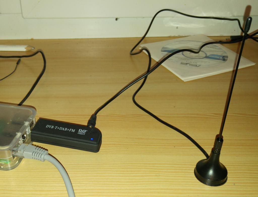
Since I didn’t buy the central screen I still needed a way to actually listen for the measurements that these sensors broadcast. It turns out cheap RTLSDR compatible DVB-T receivers can be used for that purpose with the RTL 433 application.
So I bought the receiver USB dongle with an external antenna and remote from ebay for ~10€.
Once RTL 433 is installed all you need to do to listen for the measurements is to run the rtl_433 command:
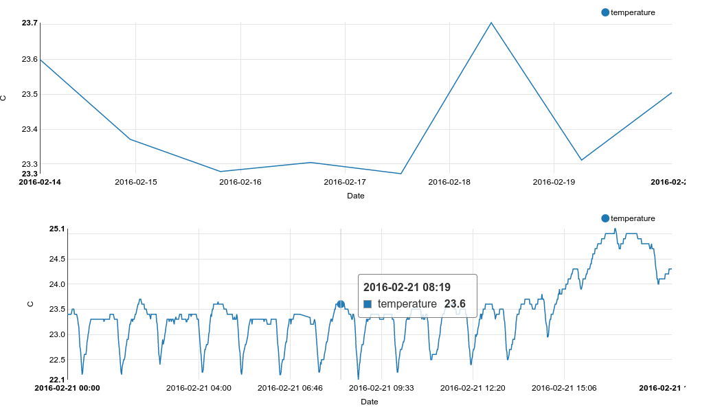
This output can be easily interfaced to whatever system you use for home automation. My graphs look like this:
My receiver is located on the second floor and the furthest sensor is about 20 meters away through 2 concrete floors and there don’t seem to be any communication problems so far.
One of the sensors came with a faulty radio that I had to replace, but more on that in a separate posting later.