Lately I have spent some time with a friend on building a temperature sensor network for my house. We used CAT5 cables for the wiring and DS18B20+ digital temperature sensors (~2.4€ a piece).
The network runs in two branches and is powered directly from the serial port so the sensors run on the phantom power.
The serial port connector is based on a schematic from this article (in Estonian). It’s actually connected to a serial-to-USB converter which is plugged into the powered USB hub which in turn is plugged into the Beagleboard. I use the digitemp utility to read the sensors.
Since we used CAT5 cables there are still 6 wires left that can be used if we need to transmit external power for higher power actuators and/or sensors in the future.
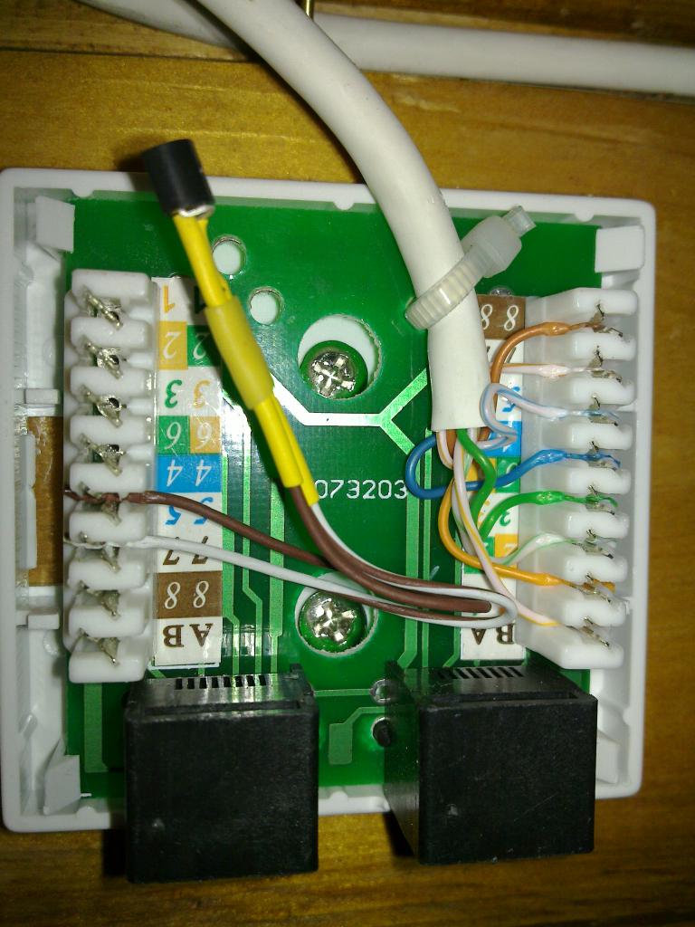
The connection points to the one-wire network are done with RJ45 surface wall mount boxes.
Here’s a picture of one splitter box for sensor connections and one sensor embedded directly into the box:
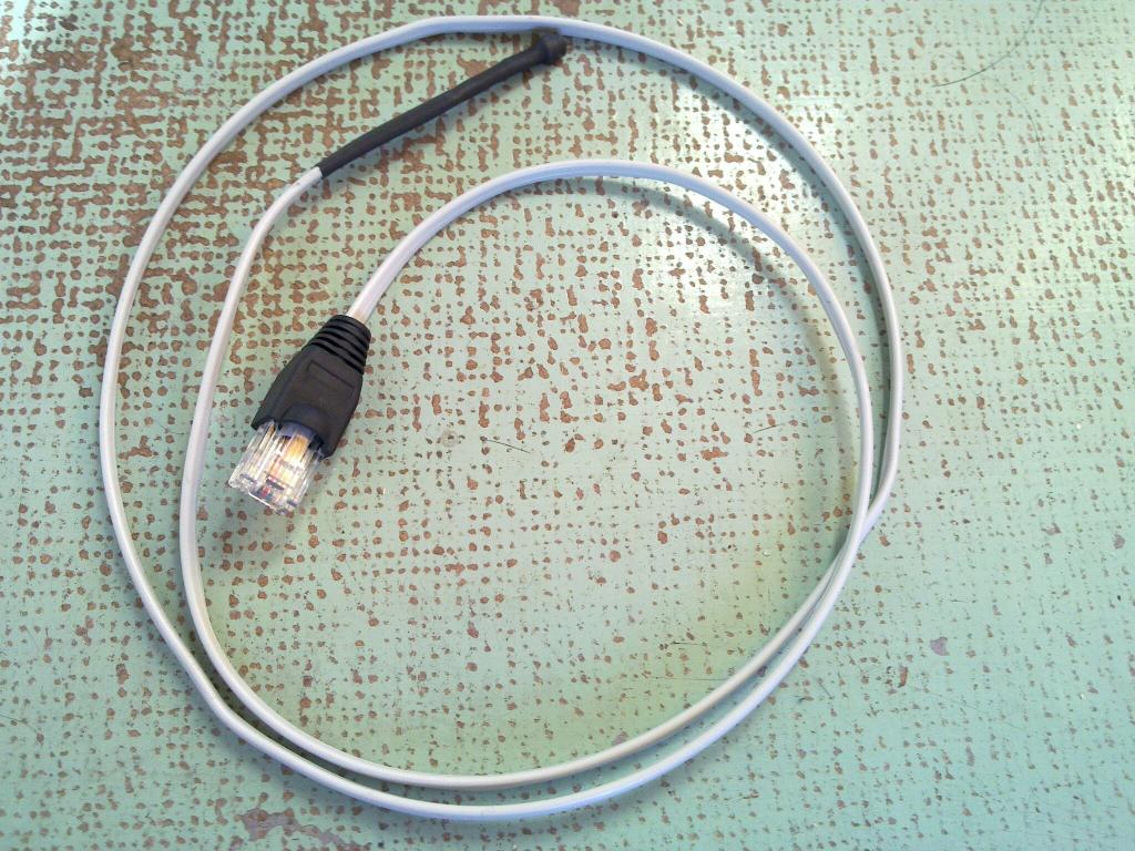
Here’s what the sensor cables look like:

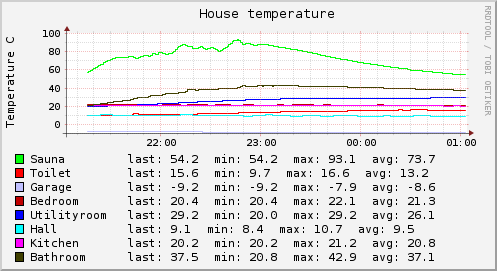
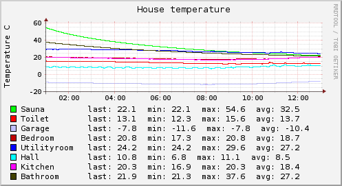
And finally here are a couple of graphs from last night:
Live data is available @ pachube.


Nice, but few ideas.
1-Wire works best when you use single non-branched linear bus with master on the one end. I heard that sensor connections should be <3m in length. This avoids reflections.
With growing network, you also want to replace serial port hack-adapter with something better. I use special chip Maxim offers, DS2480B (1-Wire to 5V / 3.3V TTL), connected to MAX232, then to serial port.
There is also USB 1-Wire direct chip, DS9490. And I2C one.
Interesting 1-Wire switching chip DS2409 is gone, though. This did master / slave switch based on 1-Wire command, basically simple electrical switch.
There also things like this to buy:
http://www.ibuttonlink.com/linkusb.aspx
And adapters for serial and USB are available from Maxim too.
Also, I’d power sensors all the time when possible. And wouldn’t modify sensors for permanent parasitic mode like on picture. Eh, I even use sockets for them.
And I’m thinking optical isolation and some kind of transient voltage protection for my network. So far, nothing done on that.
Further reading:
http://www.maxim-ic.com/app-notes/index.mvp/id/148
Maxim APPLICATION NOTE 148
Guidelines for Reliable Long Line 1-Wire® Networks