Tag Archives: domotics

adding networking to your projects

If you want to add ethernet networking to your Arduino based project following are the conventional solutions:

One of the problems with these options is that they don’t support DHCP so you have to hardcode your IP address in the firmware. Besides they seem to cost too much – for this kind of money it would be cheaper to get wireless shields.

One alternative that I have come accros is to use self contained ethernet to serial bridges, while these might not be any cheaper from the previously mentioned options, they are more powerful.
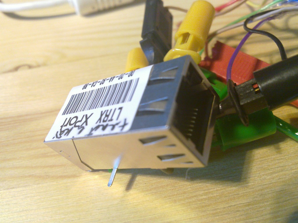
These modules are not much larger than the RJ45 socket itself and are extremelly easy to interface to any controller. Support exists for TCP, UDP, DHCP, SNMP, AES encryption and you can actually configure it to send e-mail when IO pin is triggered so for some extremelly simple applications you might be able to avoid the controller alltogether. What I’m talking about is the XPort from Lantronix.

lantronix xport

I happen to have one laying around since we used this in one of the projects many years ago. Nowadays I think you should be able to get one for ~30€ if you search long enough. There’s also a newer generation available called XPort PRO that has full linux running inside of it which allows you to do far more but costs far too much for me (~60€).

There’s also a cheaper and very powerful alternative from Digi called Digi Connect ME 9210 with full Linux running inside it (39€). It has more pins and you should be able to do things like bridging 1-wire sensor network to ethernet without any external controller. I have no experiences with that device though and haven’t found any useful discussions about it so far.

So anyway to get the XPort up and running you first have to give it an IP address. There are basically 2 ways of doing this – either with DHCP (the easy method) or over serial.

Since I wanted to learn a bit about using my Bus Pirate I used it to communicate with the serial port and verify that I can actually enter the serial setup if I wanted to.

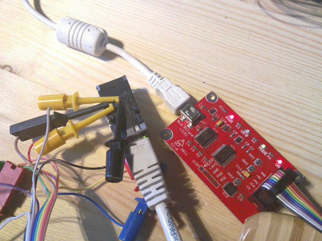
Here’s how I connected the XPort and Bus Pirate:

Bus Pirate XPort
GND 1
+3.3V 2
MOSI 4
MISO 5

Here’s how it looks like:
xport and bus pirate

To enter the serial setup you would have to do something like this:

$ picocom -b 115200 -p n -d 8 /dev/ttyUSB0
picocom v1.4
 
port is        : /dev/ttyUSB0
flowcontrol    : none
baudrate is    : 115200
parity is      : none
databits are   : 8
escape is      : C-a
noinit is      : no
noreset is     : no
nolock is      : no
send_cmd is    : ascii_xfr -s -v -l10
receive_cmd is : rz -vv
 
Terminal ready
 
HiZ>b
Set serial port speed: (bps)
 1. 300
 2. 1200
 3. 2400
 4. 4800
 5. 9600
 6. 19200
 7. 38400
 8. 57600
 9. 115200
10. BRG raw value
 
(9)>5
Adjust your terminal
Space to continue
 
Thanks for using picocom
 
$ picocom -b 9600 -p n -d 8 /dev/ttyUSB0
picocom v1.4
 
port is        : /dev/ttyUSB0
flowcontrol    : none
baudrate is    : 9600
parity is      : none
databits are   : 8
escape is      : C-a
noinit is      : no
noreset is     : no
nolock is      : no
send_cmd is    : ascii_xfr -s -v -l10
receive_cmd is : rz -vv
 
Terminal ready
HiZ>m
1. HiZ
2. 1-WIRE
3. UART
4. I2C
5. SPI
6. 2WIRE
7. 3WIRE
8. LCD
9. DIO
x. exit(without change)
 
(1)>3
Set serial port speed: (bps)
 1. 300
 2. 1200
 3. 2400
 4. 4800
 5. 9600
 6. 19200
 7. 38400
 8. 57600
 9. 115200
10. BRG raw value
 
(1)>5
Data bits and parity:
 1. 8, NONE *default
 2. 8, EVEN
 3. 8, ODD
 4. 9, NONE
(1)>
Stop bits:
 1. 1 *default
 2. 2
(1)>
Receive polarity:
 1. Idle 1 *default
 2. Idle 0
(1)>
Select output type:
 1. Open drain (H=Hi-Z, L=GND)
 2. Normal (H=3.3V, L=GND)
 
(1)>2
Ready
UART>W%:1000 0x78:100 %:100 0x0D 0x0A (2)
Power supplies ON
DELAY 1000ms
WRITE: 0x78 0x78 0x78 0x78 0x78 0x78 0x78 0x78 0x78 0x78 0x78 0x78 0x78 0x78 0x78 0x78 0x78 0x78 0x78 0x78 0x78 0x78 0x78 0x78 0x78 0x78 0x78 0x78 0x78 0x78 0x78 0x78 0x78 0x78 0x78 0x78 0x78 0x78 0x78 0x78 0x78 0x78 0x78 0x78 0x78 0x78 0x78 0x78 0x78 0x78 0x78 0x78 0x78 0x78 0x78 0x78 0x78 0x78 0x78 0x78 0x78 0x78 0x78 0x78 0x78 0x78 0x78 0x78 0x78 0x78 0x78 0x78 0x78 0x78 0x78 0x78 0x78 0x78 0x78 0x78 0x78 0x78 0x78 0x78 0x78 0x78 0x78 0x78 0x78 0x78 0x78 0x78 0x78 0x78 0x78 0x78 0x78 0x78 0x78 0x78
DELAY 100ms
WRITE: 0x0D
WRITE: 0x0A
Raw UART input
Any key to exit
 
*** basic parameters
Hardware: Ethernet TPI
IP addr - 0.0.0.0/DHCP/BOOTP/AutoIP, no gateway set
DHCP device name : not set
 
*** Security
SNMP is              enabled
SNMP Community Name: public
Telnet Setup is      enabled
TFTP Download is     enabled
Port 77FEh is        enabled
Web Server is        enabled
Web Setup is         enabled
ECHO is              disabled
Encryption is        disabled
Enhanced Password is disabled
Port 77F0h is        enabled
 
*** Channel 1
Baudrate 9600, I/F Mode 4C, Flow 00
Port 10001
Connect Mode : C0
Send '+++' in Modem Mode enabled
Auto increment source port disabled
Remote IP Adr: --- none ---, Port 00000
Disconn Mode : 00
Flush   Mode : 00
 
*** Expert
TCP Keepalive    : 45s
ARP cache timeout: 600s
High CPU performance: disabled
Monitor Mode @ bootup : enabled
HTTP Port Number : 80
SMTP Port Number : 25
MTU Size: 1400
Alternate MAC: disabled
Ethernet connection type: auto-negotiate
 
*** E-mail
Mail server: 0.0.0.0
Unit       :
Domain     :
Recipient 1:
Recipient 2: 
 
- Trigger 1
Serial trigger input: disabled
  Channel: 1
  Match: 00,00
Trigger input1: X
Trigger input2: X
Trigger input3: X
Message :
Priority: L
Min. notification interval: 1 s
Re-notification interval  : 0 s
 
- Trigger 2
Serial trigger input: disabled
  Channel: 1
  Match: 00,00
Trigger input1: X
Trigger input2: X
Trigger input3: X
Message :
Priority: L
Min. notification interval: 1 s
Re-notification interval  : 0 s
 
- Trigger 3
Serial trigger input: disabled
  Channel: 1
  Match: 00,00
Trigger input1: X
Trigger input2: X
Trigger input3: X
Message :
Priority: L
Min. notification interval: 1 s
Re-notification interval  : 0 s
 
Change Setup:
  0 Server
  1 Channel 1
  3 E-mail
  5 Expert
  6 Security
  7 Defaults
  8 Exit without save
  9 Save and exit            Your choice ?

At this point you could go on configuring the device over the serial connection but it’s a bit incovenient so I just gave it an IP with DHCP and used the web interface for configuring.

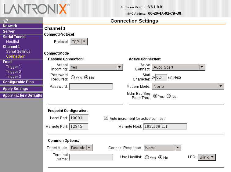
lantronics: channel connection

So with this configuration the XPort will connect to TCP port 12345 on 192.168.1.1 right after restart and we can use this channel to talk over serial port.
To test it let’s bind netcat on the 192.168.1.1:

$ nc -l 12345

And from the bus pirate shell we have to exit the monitor mode, reset the device and enter the serial bridge mode:

UART>w
Power supplies OFF
UART>W
Power supplies ON
UART>(1)
UART bridge
Reset to exit
Are you sure? y
 
test

You should now see test on the netcat shell and anything that wou write into the netcat session should show up on the buspirate shell.
weather station

I’m slowly expanding my home automation systems and the latest addition to that is this weather station.

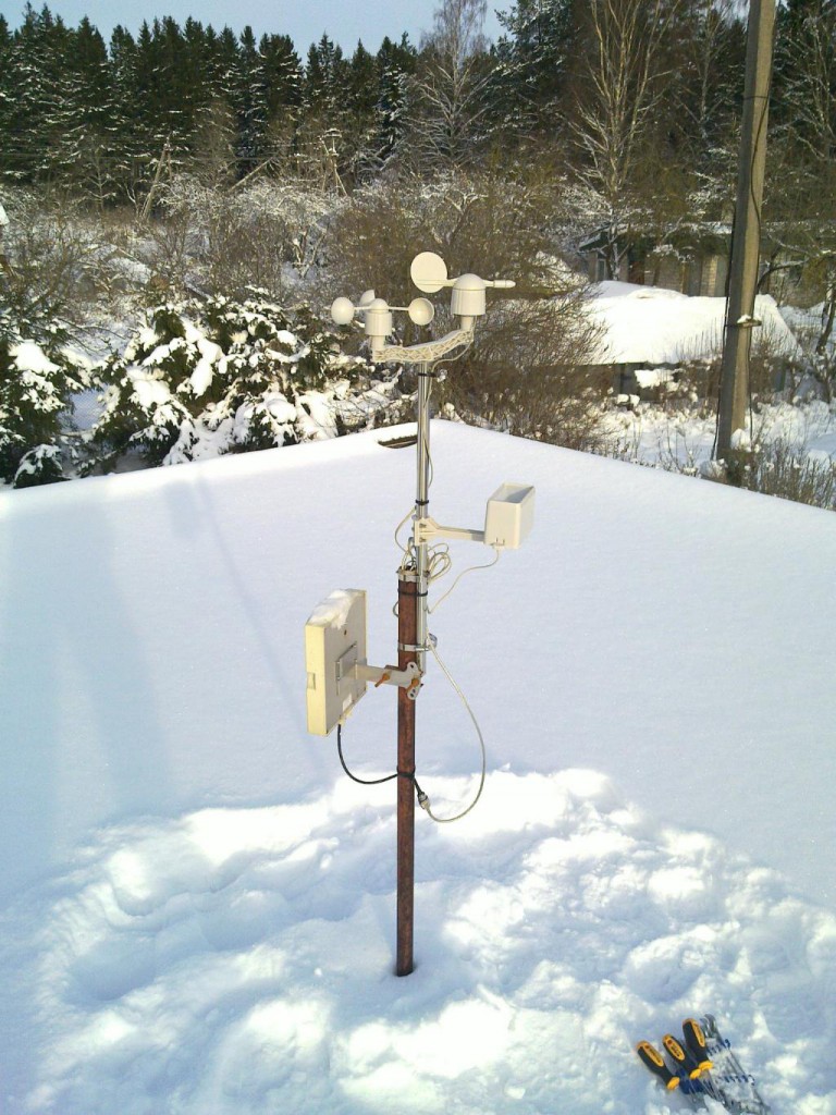
weather_station_20120129_003

The large rectangular thing in the lowest position on the antenna pole is a WIFI panel antenna.

I decided to add the weather station primarily in order to measure wind speeds so that my scripts would be able to make better decisions about closing and opening the greenhouse windows. I’m not so much worried about keeping optimal temperature in there but rather about making sure that the windows won’t get ripped off on a windy day. Another good reason is that I just like to have a lot of data and nice graphs 🙂

I wanted a relatively cheap and open weather station that I could integrate into my setup without too much effort. The closest match seemed to be this one that is sold by Sparkfun. It has an anemometer, wind vane and rain gauge. Interfacing it with a microcontroller is very simple since the wind speed and rain gauge are just Reed switches and the wind vane changes resistance. The only external component that you need is a 10k ohm resistor for the wind vane and of course some kind of microcontroller to take the measurements.

I ordered mine for 60€ from Watterott electronics which is a German shop that sells a lot of Sparkfun stuff among other things.

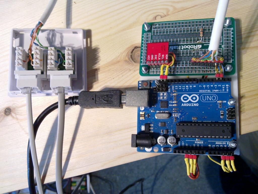
I hooked it up to an Arduino Uno using a small library that I wrote and connected that in turn over a USB cable to a beagleboard that serves as a controller for my home automation stuff.

controller_20120129_001

The small red board on this picture is a BMP085 barometric pressure sensor.

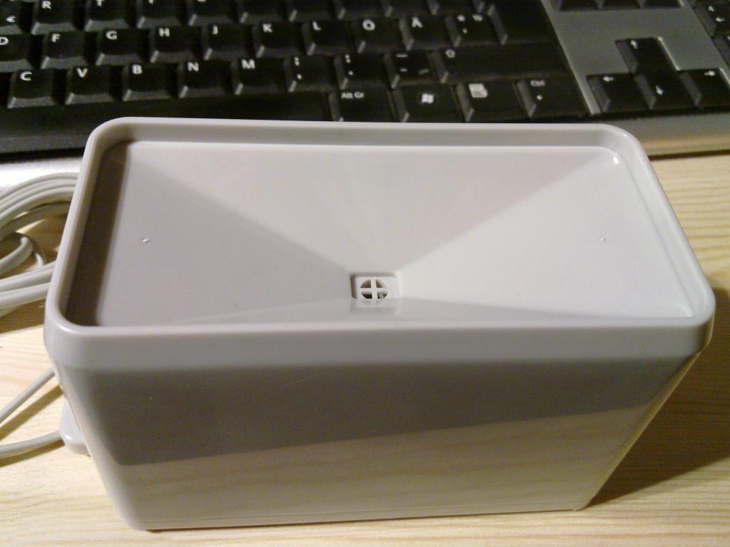
In general the weather station seems to work well enough. I’m not entirelly sure about the correctness of the measurements from the rain gauge since I see some rain measurements even though it has been constantly below -20 degs celcius here which obviously rules out rain. Here’s what the rain gauge looks like:

rain_gauge_ext_20120121_002

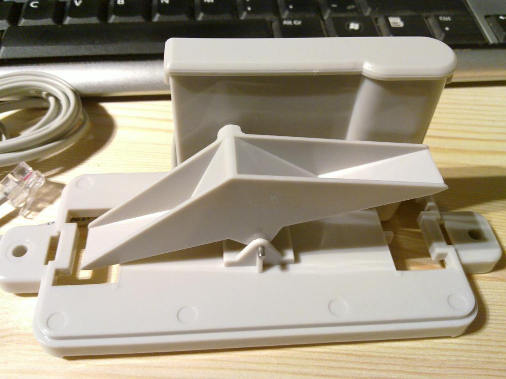
Inside you will find a seesaw with 2 buckets with a magnet in the pivot that triggers contact in the Reed switch every time the equilibrium position is changed.
rain_gauge_int_20120121_001

While the design of the rain gauge is beautiful in its simplicity it doesn’t seem to be very precise. For example sometimes the other end will bounce right back after emptying and I have no theory yet about the reason behind the random small measurements that I currently get from it.

Anyway, here’s some real time wind information from my weather station through open.sen.se and pachube:

smart energy

Lately I have been hacking on the home automation project which should at some point tie together my current ad-hoc house and greenhouse control systems. One part of that system will be energy usage optimization with wireless smartplugs, which uses Plugwise smartplugs and the python-plugwise library that I wrote. The main (and more or less the only :-)) appliance that I can make energy savings on using automation is the electric boiler. It’s an old 40-50l heater that hasn’t been cleaned for at least 3 years so it probably contains a lot of limescale and sludge which causes it to use far more power that it should. Hopefully I will get around to cleaning it soon.

I haven’t implemented any fancy logic for controlling it yet and instead I just use a simple crontab that switches the boiler on for 3 hours total each day – somewhere around when we leave for work and again before we get back home.

So far it seems to be enough to provide hot water for 2 persons on working days and it wastes around 2 times less power than it would if it was permanently switched on:
boiler_energy_usage

So assuming this difference holds true for larger periods of time I will get energy savings of ~4kWh per day. If I only use this control method on working days it will give me somewhere around 80kWh savings per month. Currently I pay 0.1026 € per kWh so I should save somewhere around 8 € per month, and 96 € per year on this appliance. So these smartplugs should pay for themselves in about 1.5 years. Currently Estonia has the cheapest price of electricity in Europe which can only go up as the energy market opens up and hidden subsidities are removed so the savings will probably be even more substantial in the not so distant future.

house sensor network

Lately I have spent some time with a friend on building a temperature sensor network for my house. We used CAT5 cables for the wiring and DS18B20+ digital temperature sensors (~2.4€ a piece).

The network runs in two branches and is powered directly from the serial port so the sensors run on the phantom power.
The serial port connector is based on a schematic from this article (in Estonian). It’s actually connected to a serial-to-USB converter which is plugged into the powered USB hub which in turn is plugged into the Beagleboard. I use the digitemp utility to read the sensors.

Since we used CAT5 cables there are still 6 wires left that can be used if we need to transmit external power for higher power actuators and/or sensors in the future.

The connection points to the one-wire network are done with RJ45 surface wall mount boxes.
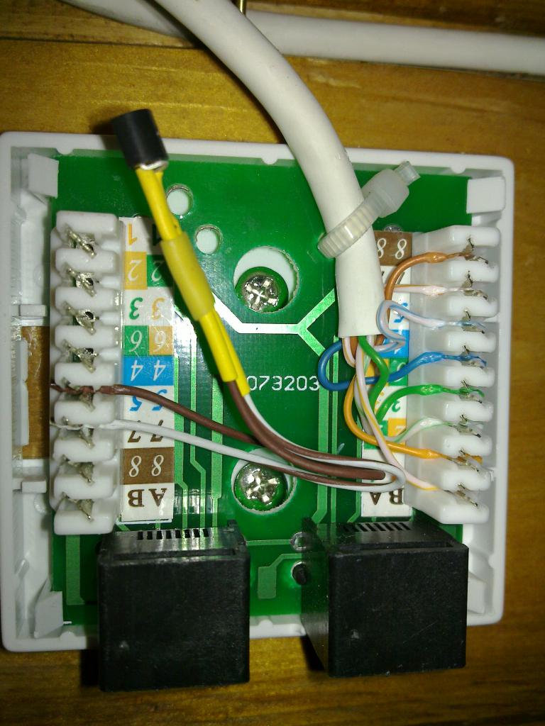
Here’s a picture of one splitter box for sensor connections and one sensor embedded directly into the box:

sensor_connection_small

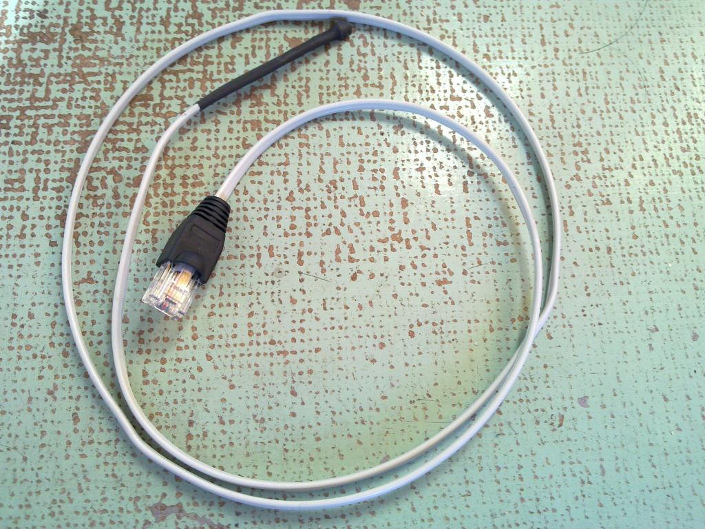
Here’s what the sensor cables look like:
sensor_small

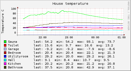
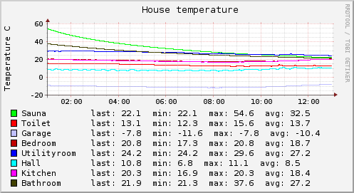
And finally here are a couple of graphs from last night:

house_temp_short

house_temp_long

Live data is available @ pachube.

thoughts on energy usage

I have lately spent considerable amount of time on reading various home automation related stuff from the energy efficiency front. With a goal of finding some solution that would allow me to measure and control electricity usage down to specific device. The idea being that in general people have found ways to reduce their energy consumption by ~20% if they see where it’s actually going. One interesting case study is here which shows that almost 1/4 of the energy in the measured office building is used up by the printers and coffee&vending machines account for almost half of the total energy usage.

In my case I believe I already have a pretty good idea what to optimize and I just need something cheap and open enough to do it.

I concentrated ZigBee smartplug solutions since it’s just really convenient to connect it anywhere without having to deal with the wiring and I already have some ZigBee stuff around for the greenhouse controller.

I came up with the following options:

  • Digi’s XBee Smart Plug. It’s currently priced at 84$ and seems rather developer friendly since simple Python examples are available. From my perspective the showstopper is that they only have US 110V version of this device available and I happen to live in europe where we use 220V.
  • Plogg. Currently priced at 97£ for their older version which as far as I can gather has proprietary interface and 135£ for the ZigBee Smart Energy profile compliant version, which hopefully means the interface is standardized. In addition I would probably need ZigBee USB dongle with Ember chip (34£) since as far as I understand from couple of google-translated form posts it wouldn’t probably work with my current XBee nodes. Add shipping to that and you get ~170£ which is a large amount of money for measuring and controlling just a single socket. Another thing that bothers me about this solution is that they don’t seem to be as open as Digi’s solution is – their FAQs talk about using their own commercial SDK for communication which is Windows only and costs you 125£ which is far cry from couple of lines of Python that it should be. On the bright side several people seem to have tapped the SDK communications and have simple scripts available that seem to work.
  • ePlug by 4-Noks. Seems nice but I couldn’t find any information on the pricing. Usually this means either you don’t want to know or we aren’t actually in production yet.
  • Plugwise. They provide starter kit with 2 smartplugs and USB dongle for 124€.You can buy extra plugs for around 30€ per socket. The kit also contains some software, but I have no use for that since it’s closed source and Windows only. Besides they have had a privacy fiasco with older version of that software which turned out to be sending your data to their servers without asking you first (it’s said that the current version of the windows software does contain option to turn it off). Luckily the protocol they use seems to be reverse engineered. Currently the main problem with this solution seem to be the shipping costs, they want 101.39€ for shipping that rather small package to me which is a bit outlandish considering the kit itself costs about as much and shipping it with normal air mail should cost max. 15€. Some resellers are shipping for less but their kit price itself is 20-30€ higher so there’s not much difference in the end result. Update: Plugwise was kind enough to send it with TNT which was a lot cheaper @ 17€

Then there’s the more fundamental question if controlling your devices should be done over such wireless protocols at all since it makes attacking your network that much simpler. The low power aspect doesn’t really help much against that since similarly to Bluetooth long-range attacks it can easily be worked around with well directed powerful antenna. I haven’t really looked well enough at ZigBee security aspects and neither am I security expert, but judging by how far more evolved WiFi security has been taken down several times I wouldn’t be hopeful that ZigBee security stands for long without major holes. Some attack tools are already available and the referenced presentation describes several awfully simple attacks (even simple replay attack is effective against several products!).

I don’t care much if an attacker can read my sensor network and determine how much power I use or what is the temperature in each room but being able to control central heating, sauna, water and gas valves etc. remotely is quite another thing. Another rather interesting question is what do you do when the protocol that is embedded in chips in wall sockets, lamps, switches and whatnot becomes trivially exploitable? Replace the whole thing? Reflash the firmware over the air? Some of the security stuff can be implemented in hardware for efficiency so firmware replacement wouldn’t help even if you could do that…

So in general I think I will use ZigBee for things that I don’t care about and for which randomly turning on and off doesn’t have any bad consequences. For critical things that can burn out or burn down the house if kept in too long I will use well shielded cable or no computer control at all.