another iteration of the bot

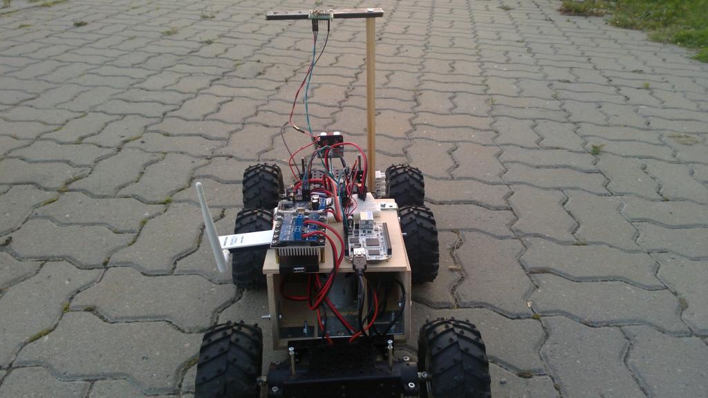
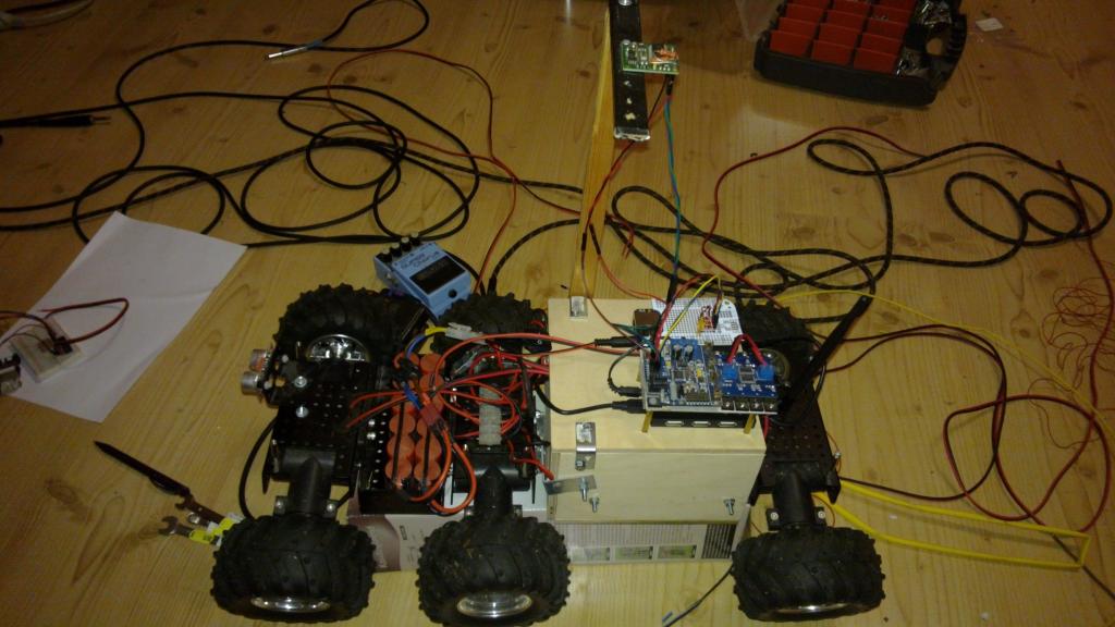
I did a bunch of hardware modifications to my bot over the weekend to make it more sturdy and to get rid of most of the loosely connected wires and the separate proto board. This is what the current iteration looks like:
ukerdis_rev_03

The main changes are:

  • 5Ah Li-ion battery replaced with two 4.6Ah NiMH batteries connected in parallel because for me the relative safety of the NiMH outweighs the capacity/weight gains of the Lithium based chemistries. I really don’t want to worry about my house burning down while charging the battery packs.
  • Replaced the Wifi dongle with a far smaller one. The new dongle is using Realtek 8192cu chipset which isn’t supported out of the box as well as the old Atheros based dongle was but I think I got it working reasonably well in the end.
  • Replaced the older generation BeagleBone with Beagle Bone Black (BBB).
  • Moved the bidirectional level shifter that is used for serial communication between the Wild Thumper Controller and BBB from separate proto board to BeagleBone proto cape.
  • Changed BBB’s power supply from 1.5A Recom 78b5.0-1.5 to 3A BEC. This change was actually done because the 3A BEC comes in a nice discreet package which is already more or less protected from the environment and having more power available is just a nice side effect.

With that the platform is stable enough that I can actually concentrate on the navigation. On that front I set up an RTK-GPS solution with RTKLIB and couple of borrowed u-blox LEA-6T evaluation kits.
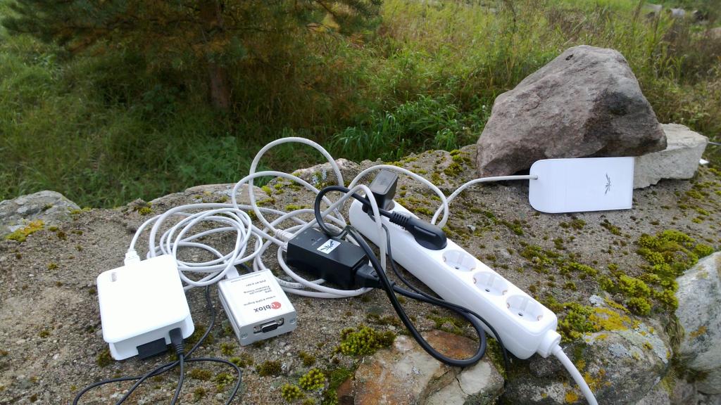
This is how my ad-hoc base station looks like:
gps_base_station_1024

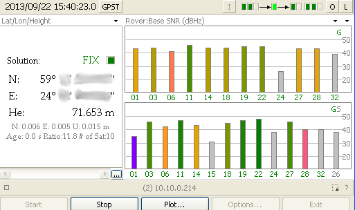
This is what the signal levels look like in RTKNAVI:
rtklib1_nocoord

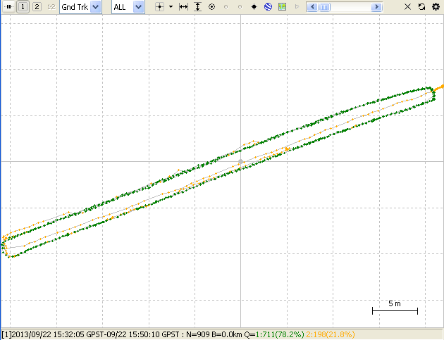
To get a good set of waypoints for testing the robot I walked a couple of times up and down my driveway:
rtkplot showing me walking up and down the driveway

The yellow dots show the FLOAT solution and the green ones show where I had the FIX solution. Basically getting the FIX solution is more precise and means the calculations that RTKLIB does, lead to a single unambiguous solution at these points.

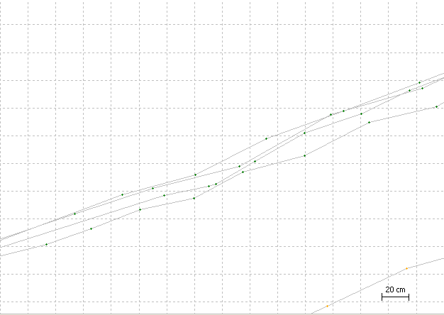
Zooming in we can see that the points from different times are at most about 20cm apart which is really good considering that I was just trying to walk in the track of the car wheel and certainly veered off a bit at times.
RTK solution closeup

two steps forward one step back

I spent most of today working on my autonomous lawnmower project. What I currently have is this:

robot_from_the_back_1024

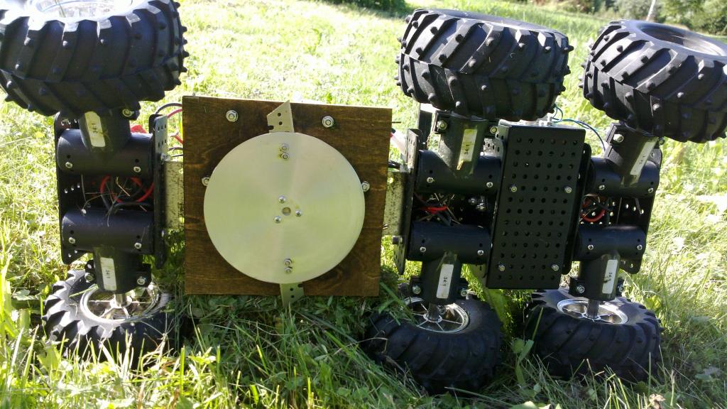
The main changes from the last prototype are the plywood box around the cutting motor and the relocation of the motor controller board to a higher place where there’s more room and less chance of getting covered with wet grass. I also switched the main controller board from Nokia N900 to Beaglebone since I had a bit of trouble getting USB host mode & WIFI working together in a stable manner on the N900. Sadly I managed to fry my Beaglebone Black so I’m currently using an older generation Beaglebone that has so far served as my main automation controller.

There are still far too many fragile loosely connected wires all over the place and if you look carefully there’s actually even a breadboard so I still have a lot of work to do before it’s ruggedized enough for its intended purpose.

an autonomous lawnmower

A while ago I moved into new house that happens to have almost 1ha of mowable land which has proven to be a great motivator to start building an autonomous lawn mower.

Of course there are many commercial robot mowers available off the shelf so why didn’t just buy one?

First of all that wouldn’t be neither fun nor educational but it also seems to cost an arm and a leg (pun intended). Most seem to be specified for somewhere around 2500 m^2 and cost between 1-2k EUR. Going by these numbers I would need 4 of these to cover my yard which amounts to far more than I’m willing to pay for automating mowing.

It’s interesting that these robots seem to be really simple and do not contain much of anything.
They just drive randomly around the area that you have fenced with a perimeter wire and drive on the wire to get to the charging station when empty. There’s no navigation whatsoever and the only sensors are bumpers and tilt switches. Safety is achieved by having a rather weak cutter that has small blades and is hidden deep under the mower.
It’s supposed to be constantly cutting so it only has to nibble a couple of mm of grass each time around so having a weak cutter works out just fine.

I imagine the bill of materials for one of these won’t be more than ~300 EUR so the margins must be huge.

So in order to build an autonomous lawnmower you don’t really need much. One of my favourite DIY builds doesn’t even have a microcontroller.

I want to build something that actually navigates though so I will use GPS for navigation instead of the perimeter wire which will make my mower a bit more costly and complex to build.
High precision GPS however is an topic in itself so more on that in a separate posting later.

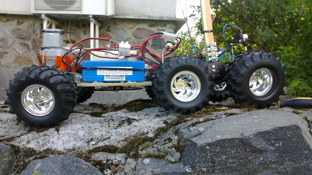
first proto sideview 08 2013

What I currently have is a simple radio controlled mower built around 6WD Wild Thumper platform that I had lying around. I also plan to use assortment of other sensors that I happen to have. While in total these components cost as much as a good commercial mower the result will also be far more interesting and since I have acquired these components over many years the cost is mostly long forgotten.
If i get it running as well as I like then I will try to build the next version from cheaper components and materials.

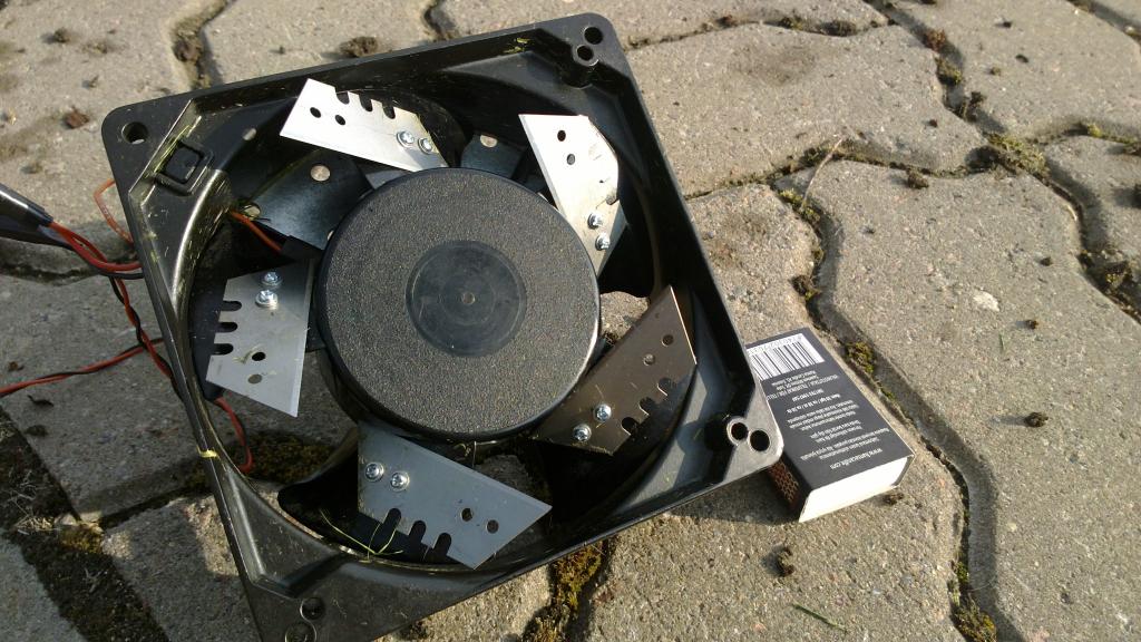
For the first cutter prototype I just attached a couple of blades to the largest server fan that I could find in the scrapheap:
first proto of the cutter
While it looks evil it didn’t cut all that well so it was back to the drawing board.

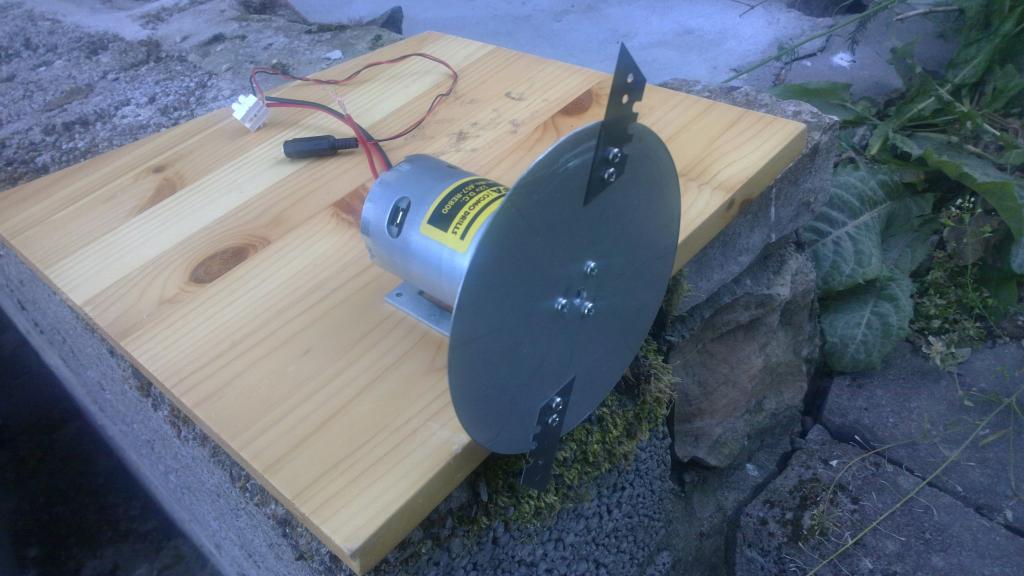
Next I used a really powerful cordless drill motor with a blade holder disk cut out of aluminium sheet.
cutter_proto2_on_testbench_xx072013_resized
I have no idea what these blades are really meant for but they are rather cheap and available in most local hardware stores.
This cutter proved to be really effective and can easily cut even long grass.

So all I had to do was to create a mowing section for my Wild Thumper chassis:
first proto underside

Here’s a video of the first mowing test which went far better than I expected:

All ducks are wearing dog masks

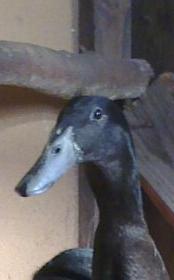
Since our new place has a rather large hen house we decided to make use of it and got ourselves some indian runner ducks. These ducks are a bit unconventional
because they walk almost upright (almost like penguins) and are rather fun to watch because of that.
They should also be great egg layers but I can’t comment on that yet since they are a bit young for that.

indian runner ducks

dogmask

PS. in case you don’t get the dogmask reference here’s an explanation.

some random notes

maybe these nuggets of knowledge will help someone…

I spent almost an hour yesterday investigating why FreeBSD 9.1 hangs 1-2 minutes after bootup on Sun x4100.
Finally I noticed that powerd always came up in top right before the hang which led me to disabling ACPI throttle by adding hint.acpi_throttle.0.disabled=1 to the /boot/loader.conf file.
Everything has worked fine since that.
I haven’t tried any other FreeBSD versions on that hardware so I have no idea if the problem is present with the older versions of the OS too.

Just out of curiosity I measured power consumption of this machine, here are the results:

  • turned off, PSU fans spinning: ~35W
  • cold start, fans running in high speed for about a minute before BIOS appears: ~200W
  • FreeBSD idling, 4 cores running at 1Ghz: ~150W
  • FreeBSD under full load (buildworld -j16), 4 cores running at 2.2Ghz: ~250W

On a completely unrelated note, I spent some time configuring IPv6 on a dedicated server rented through Hetzner’s serverbidding process.
All the tutorials talking about Hetzner specific FreeBSD IPv6 configuration seemed to be rather complicated.

Well it seems Hetzner has since made their IPv6 network setup simpler and default routers are now always at link local address fe80::1 so all that I had to add to the /etc/rc.conf to get things working under FreeBSD 9.0 is something along the lines of:

ipv6_enable="YES"
ipv6_default_interface="re0"
ipv6_defaultrouter="fe80::1%re0"
ipv6_ifconfig_re0="2001:db8:a0:80a1::2 prefixlen 64"

adding networking to your projects

If you want to add ethernet networking to your Arduino based project following are the conventional solutions:

One of the problems with these options is that they don’t support DHCP so you have to hardcode your IP address in the firmware. Besides they seem to cost too much – for this kind of money it would be cheaper to get wireless shields.

One alternative that I have come accros is to use self contained ethernet to serial bridges, while these might not be any cheaper from the previously mentioned options, they are more powerful.
These modules are not much larger than the RJ45 socket itself and are extremelly easy to interface to any controller. Support exists for TCP, UDP, DHCP, SNMP, AES encryption and you can actually configure it to send e-mail when IO pin is triggered so for some extremelly simple applications you might be able to avoid the controller alltogether. What I’m talking about is the XPort from Lantronix.
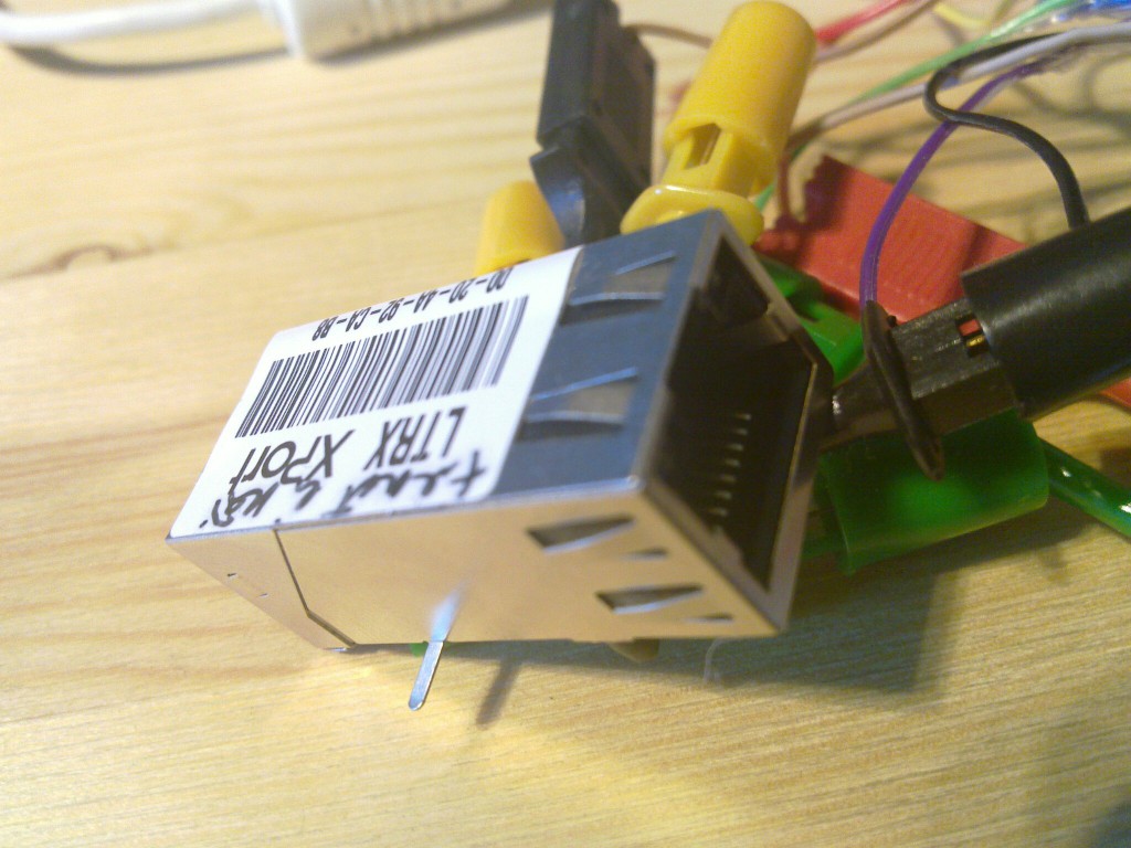
lantronix xport

I happen to have one laying around since we used this in one of the projects many years ago. Nowadays I think you should be able to get one for ~30€ if you search long enough. There’s also a newer generation available called XPort PRO that has full linux running inside of it which allows you to do far more but costs far too much for me (~60€).

There’s also a cheaper and very powerful alternative from Digi called Digi Connect ME 9210 with full Linux running inside it (39€). It has more pins and you should be able to do things like bridging 1-wire sensor network to ethernet without any external controller. I have no experiences with that device though and haven’t found any useful discussions about it so far.

So anyway to get the XPort up and running you first have to give it an IP address. There are basically 2 ways of doing this – either with DHCP (the easy method) or over serial.

Since I wanted to learn a bit about using my Bus Pirate I used it to communicate with the serial port and verify that I can actually enter the serial setup if I wanted to.

Here’s how I connected the XPort and Bus Pirate:

Bus Pirate XPort
GND 1
+3.3V 2
MOSI 4
MISO 5

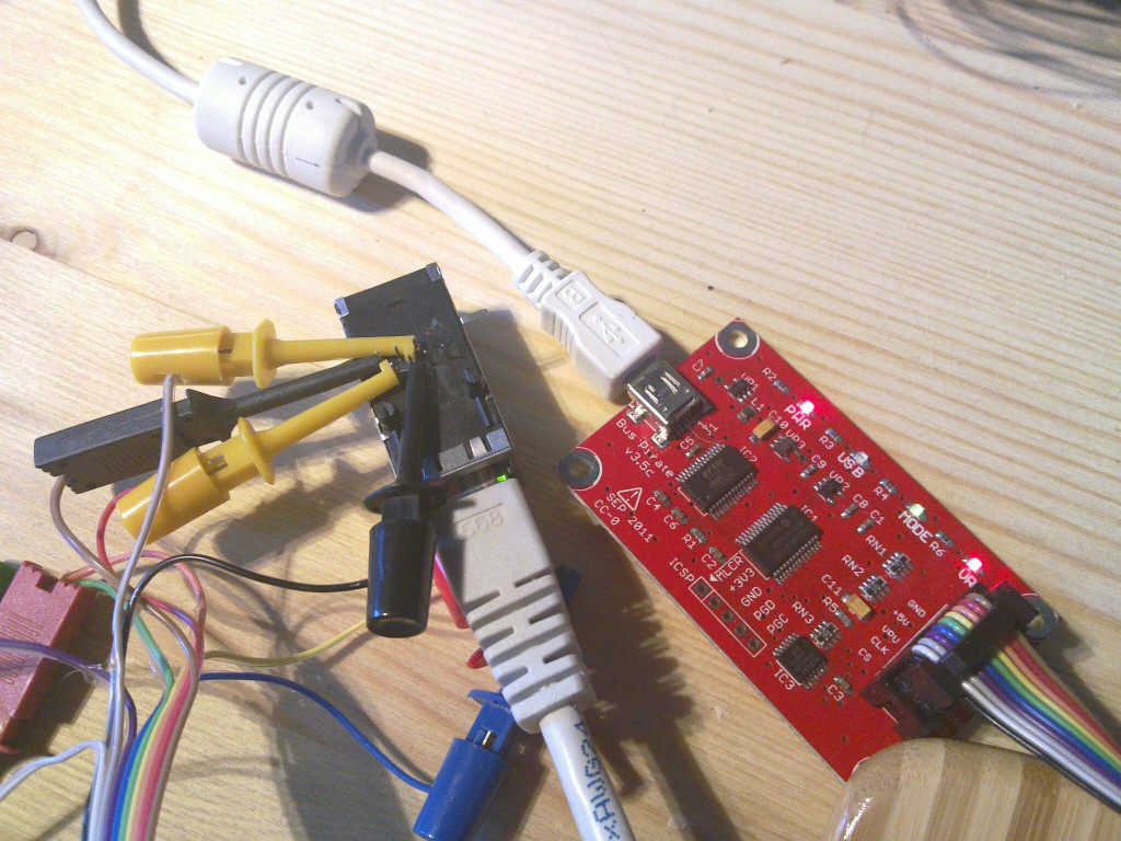
Here’s how it looks like:
xport and bus pirate

To enter the serial setup you would have to do something like this:

$ picocom -b 115200 -p n -d 8 /dev/ttyUSB0
picocom v1.4
 
port is        : /dev/ttyUSB0
flowcontrol    : none
baudrate is    : 115200
parity is      : none
databits are   : 8
escape is      : C-a
noinit is      : no
noreset is     : no
nolock is      : no
send_cmd is    : ascii_xfr -s -v -l10
receive_cmd is : rz -vv
 
Terminal ready
 
HiZ>b
Set serial port speed: (bps)
 1. 300
 2. 1200
 3. 2400
 4. 4800
 5. 9600
 6. 19200
 7. 38400
 8. 57600
 9. 115200
10. BRG raw value
 
(9)>5
Adjust your terminal
Space to continue
 
Thanks for using picocom
 
$ picocom -b 9600 -p n -d 8 /dev/ttyUSB0
picocom v1.4
 
port is        : /dev/ttyUSB0
flowcontrol    : none
baudrate is    : 9600
parity is      : none
databits are   : 8
escape is      : C-a
noinit is      : no
noreset is     : no
nolock is      : no
send_cmd is    : ascii_xfr -s -v -l10
receive_cmd is : rz -vv
 
Terminal ready
HiZ>m
1. HiZ
2. 1-WIRE
3. UART
4. I2C
5. SPI
6. 2WIRE
7. 3WIRE
8. LCD
9. DIO
x. exit(without change)
 
(1)>3
Set serial port speed: (bps)
 1. 300
 2. 1200
 3. 2400
 4. 4800
 5. 9600
 6. 19200
 7. 38400
 8. 57600
 9. 115200
10. BRG raw value
 
(1)>5
Data bits and parity:
 1. 8, NONE *default
 2. 8, EVEN
 3. 8, ODD
 4. 9, NONE
(1)>
Stop bits:
 1. 1 *default
 2. 2
(1)>
Receive polarity:
 1. Idle 1 *default
 2. Idle 0
(1)>
Select output type:
 1. Open drain (H=Hi-Z, L=GND)
 2. Normal (H=3.3V, L=GND)
 
(1)>2
Ready
UART>W%:1000 0x78:100 %:100 0x0D 0x0A (2)
Power supplies ON
DELAY 1000ms
WRITE: 0x78 0x78 0x78 0x78 0x78 0x78 0x78 0x78 0x78 0x78 0x78 0x78 0x78 0x78 0x78 0x78 0x78 0x78 0x78 0x78 0x78 0x78 0x78 0x78 0x78 0x78 0x78 0x78 0x78 0x78 0x78 0x78 0x78 0x78 0x78 0x78 0x78 0x78 0x78 0x78 0x78 0x78 0x78 0x78 0x78 0x78 0x78 0x78 0x78 0x78 0x78 0x78 0x78 0x78 0x78 0x78 0x78 0x78 0x78 0x78 0x78 0x78 0x78 0x78 0x78 0x78 0x78 0x78 0x78 0x78 0x78 0x78 0x78 0x78 0x78 0x78 0x78 0x78 0x78 0x78 0x78 0x78 0x78 0x78 0x78 0x78 0x78 0x78 0x78 0x78 0x78 0x78 0x78 0x78 0x78 0x78 0x78 0x78 0x78 0x78
DELAY 100ms
WRITE: 0x0D
WRITE: 0x0A
Raw UART input
Any key to exit
 
*** basic parameters
Hardware: Ethernet TPI
IP addr - 0.0.0.0/DHCP/BOOTP/AutoIP, no gateway set
DHCP device name : not set
 
*** Security
SNMP is              enabled
SNMP Community Name: public
Telnet Setup is      enabled
TFTP Download is     enabled
Port 77FEh is        enabled
Web Server is        enabled
Web Setup is         enabled
ECHO is              disabled
Encryption is        disabled
Enhanced Password is disabled
Port 77F0h is        enabled
 
*** Channel 1
Baudrate 9600, I/F Mode 4C, Flow 00
Port 10001
Connect Mode : C0
Send '+++' in Modem Mode enabled
Auto increment source port disabled
Remote IP Adr: --- none ---, Port 00000
Disconn Mode : 00
Flush   Mode : 00
 
*** Expert
TCP Keepalive    : 45s
ARP cache timeout: 600s
High CPU performance: disabled
Monitor Mode @ bootup : enabled
HTTP Port Number : 80
SMTP Port Number : 25
MTU Size: 1400
Alternate MAC: disabled
Ethernet connection type: auto-negotiate
 
*** E-mail
Mail server: 0.0.0.0
Unit       :
Domain     :
Recipient 1:
Recipient 2: 
 
- Trigger 1
Serial trigger input: disabled
  Channel: 1
  Match: 00,00
Trigger input1: X
Trigger input2: X
Trigger input3: X
Message :
Priority: L
Min. notification interval: 1 s
Re-notification interval  : 0 s
 
- Trigger 2
Serial trigger input: disabled
  Channel: 1
  Match: 00,00
Trigger input1: X
Trigger input2: X
Trigger input3: X
Message :
Priority: L
Min. notification interval: 1 s
Re-notification interval  : 0 s
 
- Trigger 3
Serial trigger input: disabled
  Channel: 1
  Match: 00,00
Trigger input1: X
Trigger input2: X
Trigger input3: X
Message :
Priority: L
Min. notification interval: 1 s
Re-notification interval  : 0 s
 
Change Setup:
  0 Server
  1 Channel 1
  3 E-mail
  5 Expert
  6 Security
  7 Defaults
  8 Exit without save
  9 Save and exit            Your choice ?

At this point you could go on configuring the device over the serial connection but it’s a bit incovenient so I just gave it an IP with DHCP and used the web interface for configuring.
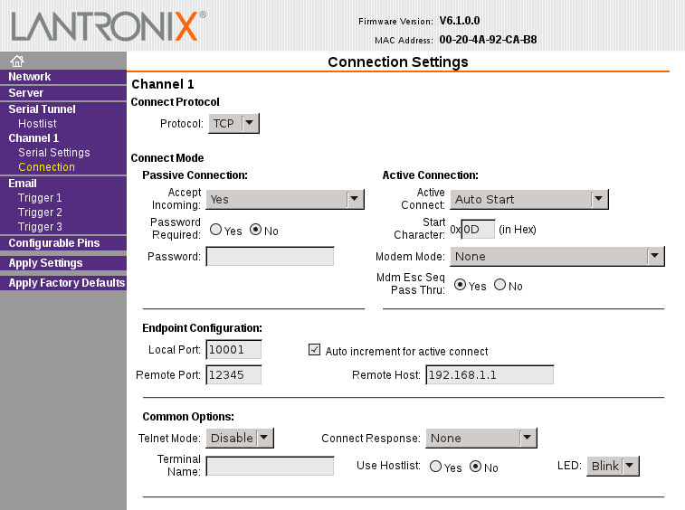
lantronics: channel connection

So with this configuration the XPort will connect to TCP port 12345 on 192.168.1.1 right after restart and we can use this channel to talk over serial port.
To test it let’s bind netcat on the 192.168.1.1:

$ nc -l 12345

And from the bus pirate shell we have to exit the monitor mode, reset the device and enter the serial bridge mode:

UART>w
Power supplies OFF
UART>W
Power supplies ON
UART>(1)
UART bridge
Reset to exit
Are you sure? y
 
test

You should now see test on the netcat shell and anything that wou write into the netcat session should show up on the buspirate shell.
weather station

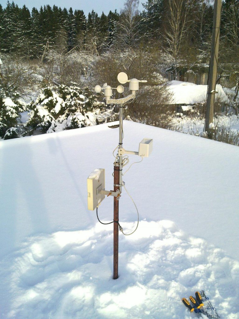
I’m slowly expanding my home automation systems and the latest addition to that is this weather station.

weather_station_20120129_003

The large rectangular thing in the lowest position on the antenna pole is a WIFI panel antenna.

I decided to add the weather station primarily in order to measure wind speeds so that my scripts would be able to make better decisions about closing and opening the greenhouse windows. I’m not so much worried about keeping optimal temperature in there but rather about making sure that the windows won’t get ripped off on a windy day. Another good reason is that I just like to have a lot of data and nice graphs 🙂

I wanted a relatively cheap and open weather station that I could integrate into my setup without too much effort. The closest match seemed to be this one that is sold by Sparkfun. It has an anemometer, wind vane and rain gauge. Interfacing it with a microcontroller is very simple since the wind speed and rain gauge are just Reed switches and the wind vane changes resistance. The only external component that you need is a 10k ohm resistor for the wind vane and of course some kind of microcontroller to take the measurements.

I ordered mine for 60€ from Watterott electronics which is a German shop that sells a lot of Sparkfun stuff among other things.

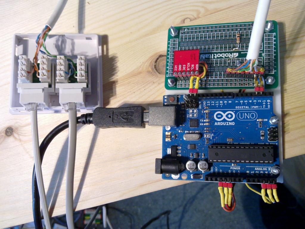
I hooked it up to an Arduino Uno using a small library that I wrote and connected that in turn over a USB cable to a beagleboard that serves as a controller for my home automation stuff.

controller_20120129_001

The small red board on this picture is a BMP085 barometric pressure sensor.

In general the weather station seems to work well enough. I’m not entirelly sure about the correctness of the measurements from the rain gauge since I see some rain measurements even though it has been constantly below -20 degs celcius here which obviously rules out rain. Here’s what the rain gauge looks like:

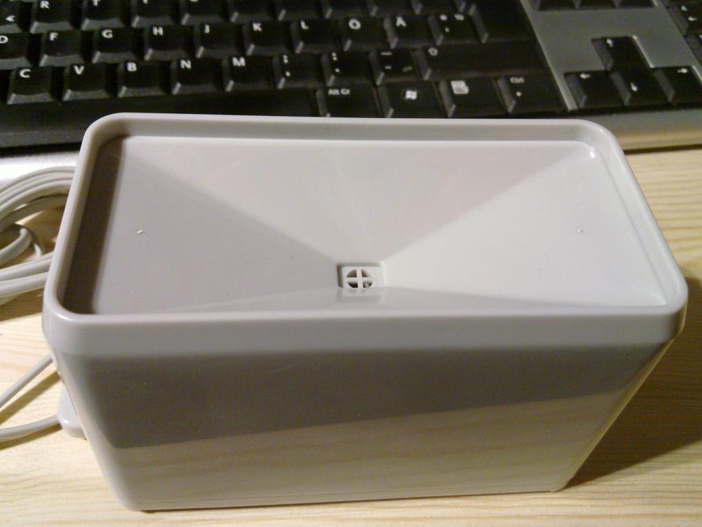
rain_gauge_ext_20120121_002

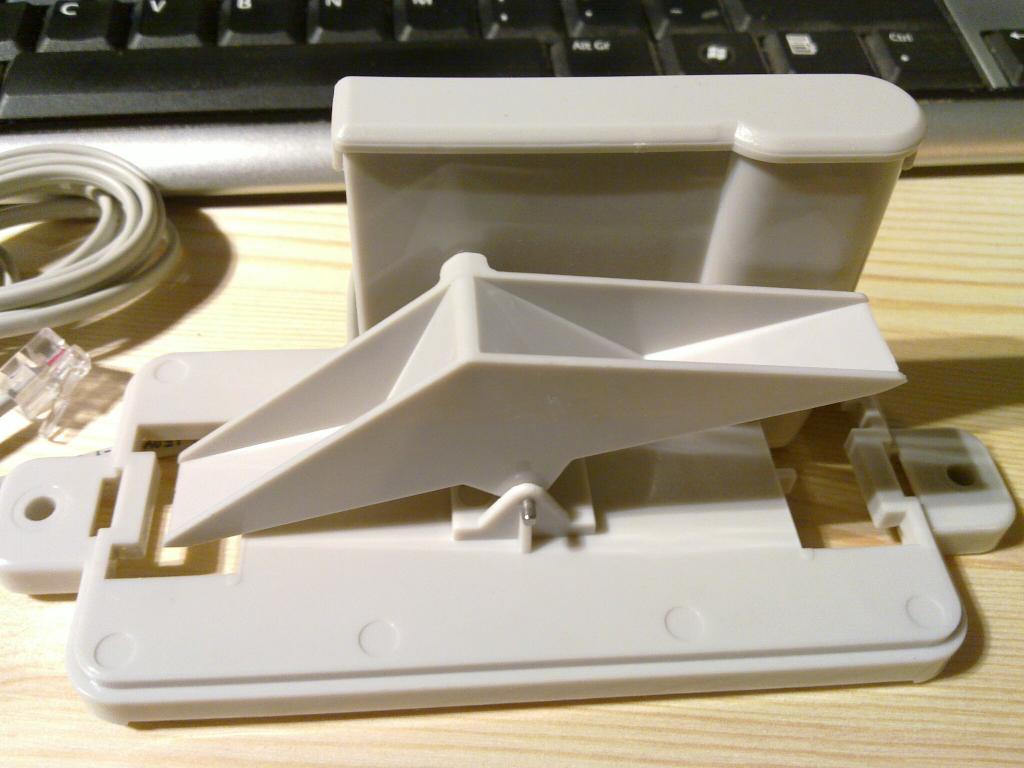
Inside you will find a seesaw with 2 buckets with a magnet in the pivot that triggers contact in the Reed switch every time the equilibrium position is changed.
rain_gauge_int_20120121_001

While the design of the rain gauge is beautiful in its simplicity it doesn’t seem to be very precise. For example sometimes the other end will bounce right back after emptying and I have no theory yet about the reason behind the random small measurements that I currently get from it.

Anyway, here’s some real time wind information from my weather station through open.sen.se and pachube:

udev rule

One thing that has bothered me for quite some time about my beagleboard home automation “server” is that the various USB dongles that use the USB to serial interface show up under random ttyUSBX device names on each reboot.

So I finally got around to writing couple of udev rules that would create necessary symlinks that will always point to the correct device.

First let’s see what devices are attached to the USB bus:

root@beaglemonitor:# lsusb
Bus 002 Device 026: ID 04fa:2490 Dallas Semiconductor DS1490F 2-in-1 Fob, 1-Wire adapter
Bus 002 Device 025: ID 13b1:0018 Linksys USB200M 10/100 Ethernet Adapter
Bus 002 Device 003: ID 0403:6001 Future Technology Devices International, Ltd FT232 USB-Serial (UART) IC
Bus 002 Device 004: ID 0403:6001 Future Technology Devices International, Ltd FT232 USB-Serial (UART) IC
Bus 002 Device 002: ID 0424:2507 Standard Microsystems Corp.
Bus 002 Device 001: ID 1d6b:0002 Linux Foundation 2.0 root hub
Bus 001 Device 001: ID 1d6b:0002 Linux Foundation 2.0 root hub

Currently this system only has two usb-serial converters attached, but both have the same ID so we have to use something more specific in order to distinquish between the two.
One way to get see what parameters are available is with lsusb -v but we will go with udevadm which gives output in a format that can be directly copy-pasted to the rule file.

root@beaglemonitor# udevadm info -a -p `udevadm info -q path -n /dev/ttyUSB1`
custom logging function 0x2a026008 registered
selinux=0
calling: info
device 0x2a0260e8 has devpath '/devices/platform/musb_hdrc/usb2/2-1/2-1.4/2-1.4:1.0/ttyUSB1/tty/ttyUSB1'
custom logging function 0x2a026008 registered
selinux=0
calling: info
device 0x2a0260e8 has devpath '/devices/platform/musb_hdrc/usb2/2-1/2-1.4/2-1.4:1.0/ttyUSB1/tty/ttyUSB1'
 
Udevadm info starts with the device specified by the devpath and then
walks up the chain of parent devices. It prints for every device
found, all possible attributes in the udev rules key format.
A rule to match, can be composed by the attributes of the device
and the attributes from one single parent device.
  looking at device '/devices/platform/musb_hdrc/usb2/2-1/2-1.4/2-1.4:1.0/ttyUSB1/tty/ttyUSB1':
    KERNEL=="ttyUSB1"
    SUBSYSTEM=="tty"
    DRIVER==""
 
device 0x2a026350 has devpath '/devices/platform/musb_hdrc/usb2/2-1/2-1.4/2-1.4:1.0/ttyUSB1'
  looking at parent device '/devices/platform/musb_hdrc/usb2/2-1/2-1.4/2-1.4:1.0/ttyUSB1':
    KERNELS=="ttyUSB1"
    SUBSYSTEMS=="usb-serial"
    DRIVERS=="ftdi_sio"
    ATTRS{latency_timer}=="1"
    ATTRS{port_number}=="0"
 
device 0x2a0265f8 has devpath '/devices/platform/musb_hdrc/usb2/2-1/2-1.4/2-1.4:1.0'
  looking at parent device '/devices/platform/musb_hdrc/usb2/2-1/2-1.4/2-1.4:1.0':
    KERNELS=="2-1.4:1.0"
    SUBSYSTEMS=="usb"
    DRIVERS=="ftdi_sio"
    ATTRS{bInterfaceNumber}=="00"
    ATTRS{bAlternateSetting}==" 0"
    ATTRS{bNumEndpoints}=="02"
    ATTRS{bInterfaceClass}=="ff"
    ATTRS{bInterfaceSubClass}=="ff"
    ATTRS{bInterfaceProtocol}=="ff"
    ATTRS{modalias}=="usb:v0403p6001d0600dc00dsc00dp00icFFiscFFipFF"
    ATTRS{supports_autosuspend}=="0"
    ATTRS{interface}=="FT232R USB UART"
 
device 0x2a026ab8 has devpath '/devices/platform/musb_hdrc/usb2/2-1/2-1.4'
  looking at parent device '/devices/platform/musb_hdrc/usb2/2-1/2-1.4':
    KERNELS=="2-1.4"
    SUBSYSTEMS=="usb"
    DRIVERS=="usb"
    ATTRS{configuration}==""
    ATTRS{bNumInterfaces}==" 1"
    ATTRS{bConfigurationValue}=="1"
    ATTRS{bmAttributes}=="a0"
    ATTRS{bMaxPower}==" 90mA"
    ATTRS{urbnum}=="488"
    ATTRS{idVendor}=="0403"
    ATTRS{idProduct}=="6001"
    ATTRS{bcdDevice}=="0600"
    ATTRS{bDeviceClass}=="00"
    ATTRS{bDeviceSubClass}=="00"
    ATTRS{bDeviceProtocol}=="00"
    ATTRS{bNumConfigurations}=="1"
    ATTRS{bMaxPacketSize0}=="8"
    ATTRS{speed}=="12"
    ATTRS{busnum}=="2"
    ATTRS{devnum}=="4"
    ATTRS{devpath}=="1.4"
    ATTRS{version}==" 2.00"
    ATTRS{maxchild}=="0"
    ATTRS{quirks}=="0x0"
    ATTRS{avoid_reset_quirk}=="0"
    ATTRS{authorized}=="1"
    ATTRS{manufacturer}=="FTDI"
    ATTRS{product}=="FT232R USB UART"
    ATTRS{serial}=="A100dj0d"
 
device 0x2a0273d0 has devpath '/devices/platform/musb_hdrc/usb2/2-1'
  looking at parent device '/devices/platform/musb_hdrc/usb2/2-1':
    KERNELS=="2-1"
    SUBSYSTEMS=="usb"
    DRIVERS=="usb"
    ATTRS{configuration}==""
    ATTRS{bNumInterfaces}==" 1"
    ATTRS{bConfigurationValue}=="1"
    ATTRS{bmAttributes}=="e0"
    ATTRS{bMaxPower}=="  2mA"
    ATTRS{urbnum}=="430"
    ATTRS{idVendor}=="0424"
    ATTRS{idProduct}=="2507"
    ATTRS{bcdDevice}=="0000"
    ATTRS{bDeviceClass}=="09"
    ATTRS{bDeviceSubClass}=="00"
    ATTRS{bDeviceProtocol}=="01"
    ATTRS{bNumConfigurations}=="1"
    ATTRS{bMaxPacketSize0}=="64"
    ATTRS{speed}=="480"
    ATTRS{busnum}=="2"
    ATTRS{devnum}=="2"
    ATTRS{devpath}=="1"
    ATTRS{version}==" 2.00"
    ATTRS{maxchild}=="7"
    ATTRS{quirks}=="0x0"
    ATTRS{avoid_reset_quirk}=="0"
    ATTRS{authorized}=="1"
 
device 0x2a027c10 has devpath '/devices/platform/musb_hdrc/usb2'
  looking at parent device '/devices/platform/musb_hdrc/usb2':
    KERNELS=="usb2"
    SUBSYSTEMS=="usb"
    DRIVERS=="usb"
    ATTRS{configuration}==""
    ATTRS{bNumInterfaces}==" 1"
    ATTRS{bConfigurationValue}=="1"
    ATTRS{bmAttributes}=="e0"
    ATTRS{bMaxPower}=="  0mA"
    ATTRS{urbnum}=="76"
    ATTRS{idVendor}=="1d6b"
    ATTRS{idProduct}=="0002"
    ATTRS{bcdDevice}=="0206"
    ATTRS{bDeviceClass}=="09"
    ATTRS{bDeviceSubClass}=="00"
    ATTRS{bDeviceProtocol}=="00"
    ATTRS{bNumConfigurations}=="1"
    ATTRS{bMaxPacketSize0}=="64"
    ATTRS{speed}=="480"
    ATTRS{busnum}=="2"
    ATTRS{devnum}=="1"
    ATTRS{devpath}=="0"
    ATTRS{version}==" 2.00"
    ATTRS{maxchild}=="1"
    ATTRS{quirks}=="0x0"
    ATTRS{avoid_reset_quirk}=="0"
    ATTRS{authorized}=="1"
    ATTRS{manufacturer}=="Linux 2.6.35.9-x9 musb-hcd"
    ATTRS{product}=="MUSB HDRC host driver"
    ATTRS{serial}=="musb_hdrc"
    ATTRS{authorized_default}=="1"
 
device 0x2a0286d8 has devpath '/devices/platform/musb_hdrc'
  looking at parent device '/devices/platform/musb_hdrc':
    KERNELS=="musb_hdrc"
    SUBSYSTEMS=="platform"
    DRIVERS=="musb_hdrc"
    ATTRS{modalias}=="platform:musb_hdrc"
    ATTRS{mode}=="a_host"
    ATTRS{vbus}=="Vbus off, timeout 1100 msec"
 
device 0x2a028a58 has devpath '/devices/platform'
  looking at parent device '/devices/platform':
    KERNELS=="platform"
    SUBSYSTEMS==""
    DRIVERS==""

As the message at the beginning of the output tells us we can use parameters from the child and one of the parents in the rule.
So assuming that I have somehow determined that at the moment device /dev/ttyUSB1 is a Plugwise dongle and I would like to create a symlink
/dev/plugwise for it in the future would lead us to the following udev rule:

KERNEL=="ttyUSB*", ATTRS{idVendor}=="0403", ATTRS{idProduct}=="6001", ATTRS{serial}=="A100dj0d", SYMLINK+="plugwise"

So lets create a configuration file for it and restart the udev:

root@beaglemonitor# echo 'KERNEL=="ttyUSB*", ATTRS{idVendor}=="0403", ATTRS{idProduct}=="6001", ATTRS{serial}=="A100dj0d", SYMLINK+="plugwise"' > /etc/udev/rules.d/zz-plugwise.rules
root@beaglemonitor# /etc/init.d/udev restart
Stopping the hotplug events dispatcher: udevd.
Starting the hotplug events dispatcher: udevd.
root@beaglemonitor# ls -alFs /dev/plugwise
0 lrwxrwxrwx 1 root root 7 Dec 24 15:14 /dev/plugwise -> ttyUSB1

Based on a similar process the other device will get the following rule:

KERNEL=="ttyUSB*", ATTRS{idVendor}=="0403", ATTRS{idProduct}=="6001", ATTRS{serial}=="A600asCw", SYMLINK+="greenhouse"