Category Archives: robotics

and hardware is the easy part…

One of my hobbies is building robots. The largest one to date is this (me for scale):

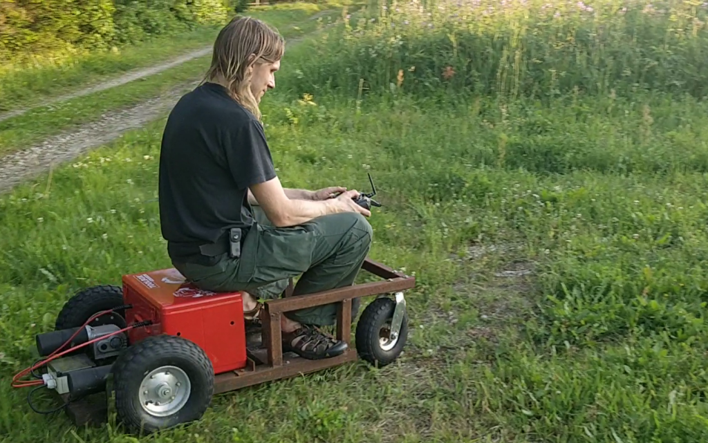
I created it as a general large platform for outdoor experimentation that would be able to take on various practical tasks in a more or less autonomous manner.
What I didn’t anticipate is how hard it is to build such a platform in a way that is both economical and reliable.

While it does work in general, the Mean Time Between Failure has proven to be somewhere in the range of an hour or so.
When something major breaks, the robot goes back to the parking lot waiting for the next season while I contemplate if I want to spend more resources on fixing it. So the progress on this project has been rather slow to put it mildly…

Anyway the first idea was to use it as an autonomous lawnmower. I did get around to doing some mowing experiments with a single blade as you can see in this video:

As you can see the mowing part works, but it isn’t particularly impressive. Adding the second cutting motor would have helped a bit as would using a single large blade with a more powerful motor like the one that is used in commercial cordless mowers like Makita DLM380.
But in general this chassis seemed just too powerful and dangerous for an autonomous mowing operation in the garden. Nowadays Ardumower seems like a much better base for autonomous mower projects.

Personally I also lost interest in the specific problem of mowing several years ago since it isn’t a personal itch anymore — I have sheep nowadays to keep the grass at a reasonable height.

So anyway I decided to repurpose the robot for watering plants in the field.
It’s something that I potentially actually need, requires quite a bit of carrying capacity and the work happens out in the field where it can’t cause that serious damage when it goes out of control. It also tried the job of the sheepdog for a while 😛

Motors

The motors that I use are really old 24V wheelchair motors. These motors seemed a really good fit for my purpose because of the high torque and generally robust construction.
They are really hard to source though at a reasonable price (new ones go for min. 400+EUR/pair) and it’s hard to connect these to any wheels that are cheap and fit for agricultural purposes.

I managed to find a local wheelchair repairman who sold a pair of these for 25EUR but the downside is that these are old used ones are rather one-off and in unknown condition. You are lucky to get a matched pair and mine had an obscure shaft with a keyslot. If one motor fails you will probably have to find another pair which likely has a bit different dimensions, shaft length, -diameter and type which would require a bit of redesign.

The spiral spring holding one of the brushes in place on one of the motors rusted through. Finding a suitable replacement spiral brush spring seemed rather hopeless so I patched it with a random spring of completely different type. It kind of works but is somewhat unreliable — it sometimes loses contact and needs a tap on the back.

During the last couple of years brushless hub motors have been coming down in price and I think nowadays I would go with these instead. Finding ones that are wide enough with at least 14.5″ diam and shipping price that wouldn’t be half the price is still a challenge though.

Wheels

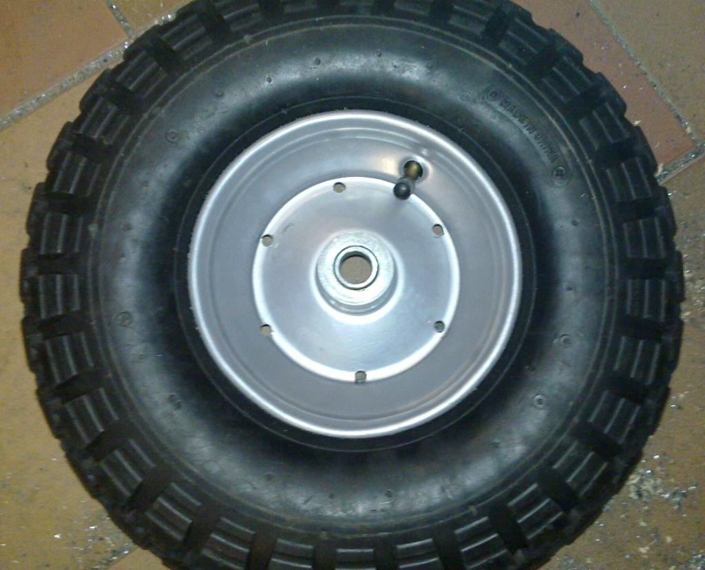
I decided to use wheelbarrow wheels since there’s a wide selection available, there are rather wide ones with a large diameter that are suitable for rugged terrain and they are cheap.
Attaching these to the shaft is tricky though, since wheelbarrow wheels are generally built with the idea that you put a rod through them which rests on a bearing.

I decided to use an industrial taped bore and just drill matching holes through the wheelbarrow wheel rim. The best rim that I found was a bit conical though, which made it almost impossible to perfectly center the taper bore on it.

To attach it to the wheelbarrow wheels I had to find a shaft key, taperlock bush for that particular shaft and key size and a fitting taper bore.
These I had to order from different suppliers from the other side of the world which took quite a while. I didn’t actually find perfectly matching ones so I had to hammer and file it a bit and you can see on the picture that the taperlock bush has actually cracked:

Looking back at the effort spent, ordering a special made one from some local metalworks company would probably have been easier and maybe even cheaper.

The battery

The first generation used two Exide ES650 lead-acid deep cycle gel batteries in series. One of these failed though a bit after the end of the warranty. I only managed to use it for a couple of hours in total over these two years because chassis-motors-wheels took unexpectedly long to complete.
That battery failed after I used it to start a car with a dead battery once, which is kind of strange.
While deep cycle batteries aren’t certainly meant for that, I don’t think getting it damaged with using it for starting once is the expected result.

Anyway, having lost one battery I had a choice of either buying a new one for the pair or switching to some other battery chemistry completely.
While still having one usable battery would have made replacing just the other somewhat simpler and certainly cheaper proposition in the near term. In the long term this looked like a dead end though.
These batteries seem to have an expected lifetime of around 5 years and the functioning one was approaching that even though it has seen barely any actual use.
Also the energy density is obviously a lot lower than for many more modern chemistries.

I didn’t like to go with Li-Ion batteries based around 18650 cells that are otherwise rather popular with DIYers, since reading the forums of the communities shows just how fickle these can be and how much attention to the detail is needed.
Treating these batteries in just the right way for them to last more than a thousand or so cycles seems to be a science in itself and there’s a chance of them bursting to flames if you do something wrong.

I contemplated LiFePo batteries which are safer and should last a bit longer (~2-3k cycles) but then I found LTO cells (Lithium titanate) cells instead.

Lithium-Titanate cells seem to be so much better for my use for many reasons:

  • around 30k cycles or around 30 years of lifetime. I didn’t want to face losing the battery again before starting to seriously use it.
  • safe to handle. It seems right next to impossible to get them to burn with puncturing, cutting, overcharging etc. You can see how much abuse they can take here.
  • you can charge them fully in 10 minutes and discharge at 10C (400A in my case)
  • cold temperatures do not reduce performance nearly as much as they do for li-ion for example. Actually these are rated for operating down to -50C. I might want to drive the robot during the winter too and when the battery is not in use with the robot it will be used for energy storage system at the birdhouse where we have outdoor temperatures.
  • over draining or over charging these isn’t as much of a problem as with other Li battery chemistries. You can just pretty much use Lead-acid charger even without BMS if you do not care about getting 100% of capacity out of it. I guess you might also lose some of the theoretical lifetime that way but having such a nice direct lead-acid replacement might be worth it.

There are also downsides of course. Specific energy of the LTO pack is a lot lower than it would be with some other Li chemistries like NMC (73Wh/kg vs. 200Wh/kg) and the price is a bit higher (around 20% for the specific setups that I compared).

So anyway here’s the LTO battery pack I ended up building:

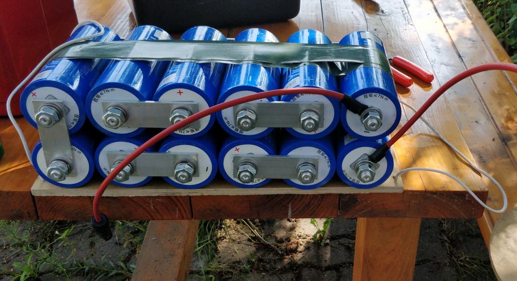
My pack consists of 12 * Yinlong 40Ah 26650 cells. The nominal voltage of these cells is 2.3V so for the pack it is 27.6V.
The busbars connecting the cells are cut from 4mm thick aluminium bar. I contemplated getting a copper bar for that but it’s harder to find and besides the threaded connectors on the cells are made of aluminium anyway.

Controller

I use Sabretooth 2x25A driver. This has worked flawlessly and has taken some serious abuse without any complaints. For example one year I forgot to remove it from the robot for the winter and I discovered it in the spring. Water had somehow gotten into the controller box and the board was frozen in ice.
Just melted it and dried… has worked without any problems.

cheap RTK-GPS hardware might soon be available!

As mentioned previously I used two loaned u-blox LEA-6T devkits for my robot mower prototype which seemed to get acceptable precision (~10-20cm) with RTK-GPS using RTKLIB. Problem with this solution was that these devkits cost around 300 EUR which is far too much for my intended usage.

Until now I planned to switch to Yuan 10 for the next prototype. Yuan 10 costs 97.60 per board (antennas not included) and uses SkyTraq S1315F-RAW chip internally which is able to output raw measurement at 5Hz.

It turns out though that there is currently an NavSpark fundraising campaign by the SkyTraq itself which, if sucessful, will get you 2 boards with this chip + active antennas for 50$. At the moment of writing more than half of the campaign time has passed and they are less than 30% funded so if you want cheap RTK-GPS to happen support them and spread the word.

Getting such an high precision GPS solution for so cheap would certainly open many new interesting usage possibilities!

PS. This RTKLIB compatible perk was actually added quite late to their project. Main goal is to produce tiny sub 20$ GPS boards that can be programmed, run at 100Mhz and have lots of usable GPIO pins, which is also awesome.

another iteration of the bot

I did a bunch of hardware modifications to my bot over the weekend to make it more sturdy and to get rid of most of the loosely connected wires and the separate proto board. This is what the current iteration looks like:
ukerdis_rev_03

The main changes are:

  • 5Ah Li-ion battery replaced with two 4.6Ah NiMH batteries connected in parallel because for me the relative safety of the NiMH outweighs the capacity/weight gains of the Lithium based chemistries. I really don’t want to worry about my house burning down while charging the battery packs.
  • Replaced the Wifi dongle with a far smaller one. The new dongle is using Realtek 8192cu chipset which isn’t supported out of the box as well as the old Atheros based dongle was but I think I got it working reasonably well in the end.
  • Replaced the older generation BeagleBone with Beagle Bone Black (BBB).
  • Moved the bidirectional level shifter that is used for serial communication between the Wild Thumper Controller and BBB from separate proto board to BeagleBone proto cape.
  • Changed BBB’s power supply from 1.5A Recom 78b5.0-1.5 to 3A BEC. This change was actually done because the 3A BEC comes in a nice discreet package which is already more or less protected from the environment and having more power available is just a nice side effect.

With that the platform is stable enough that I can actually concentrate on the navigation. On that front I set up an RTK-GPS solution with RTKLIB and couple of borrowed u-blox LEA-6T evaluation kits.
This is how my ad-hoc base station looks like:
gps_base_station_1024

This is what the signal levels look like in RTKNAVI:
rtklib1_nocoord

To get a good set of waypoints for testing the robot I walked a couple of times up and down my driveway:
rtkplot showing me walking up and down the driveway

The yellow dots show the FLOAT solution and the green ones show where I had the FIX solution. Basically getting the FIX solution is more precise and means the calculations that RTKLIB does, lead to a single unambiguous solution at these points.

Zooming in we can see that the points from different times are at most about 20cm apart which is really good considering that I was just trying to walk in the track of the car wheel and certainly veered off a bit at times.
RTK solution closeup

two steps forward one step back

I spent most of today working on my autonomous lawnmower project. What I currently have is this:

robot_from_the_back_1024

The main changes from the last prototype are the plywood box around the cutting motor and the relocation of the motor controller board to a higher place where there’s more room and less chance of getting covered with wet grass. I also switched the main controller board from Nokia N900 to Beaglebone since I had a bit of trouble getting USB host mode & WIFI working together in a stable manner on the N900. Sadly I managed to fry my Beaglebone Black so I’m currently using an older generation Beaglebone that has so far served as my main automation controller.

There are still far too many fragile loosely connected wires all over the place and if you look carefully there’s actually even a breadboard so I still have a lot of work to do before it’s ruggedized enough for its intended purpose.

an autonomous lawnmower

A while ago I moved into new house that happens to have almost 1ha of mowable land which has proven to be a great motivator to start building an autonomous lawn mower.

Of course there are many commercial robot mowers available off the shelf so why didn’t just buy one?

First of all that wouldn’t be neither fun nor educational but it also seems to cost an arm and a leg (pun intended). Most seem to be specified for somewhere around 2500 m^2 and cost between 1-2k EUR. Going by these numbers I would need 4 of these to cover my yard which amounts to far more than I’m willing to pay for automating mowing.

It’s interesting that these robots seem to be really simple and do not contain much of anything.
They just drive randomly around the area that you have fenced with a perimeter wire and drive on the wire to get to the charging station when empty. There’s no navigation whatsoever and the only sensors are bumpers and tilt switches. Safety is achieved by having a rather weak cutter that has small blades and is hidden deep under the mower.
It’s supposed to be constantly cutting so it only has to nibble a couple of mm of grass each time around so having a weak cutter works out just fine.

I imagine the bill of materials for one of these won’t be more than ~300 EUR so the margins must be huge.

So in order to build an autonomous lawnmower you don’t really need much. One of my favourite DIY builds doesn’t even have a microcontroller.

I want to build something that actually navigates though so I will use GPS for navigation instead of the perimeter wire which will make my mower a bit more costly and complex to build.
High precision GPS however is an topic in itself so more on that in a separate posting later.

first proto sideview 08 2013

What I currently have is a simple radio controlled mower built around 6WD Wild Thumper platform that I had lying around. I also plan to use assortment of other sensors that I happen to have. While in total these components cost as much as a good commercial mower the result will also be far more interesting and since I have acquired these components over many years the cost is mostly long forgotten.
If i get it running as well as I like then I will try to build the next version from cheaper components and materials.

For the first cutter prototype I just attached a couple of blades to the largest server fan that I could find in the scrapheap:
first proto of the cutter
While it looks evil it didn’t cut all that well so it was back to the drawing board.

Next I used a really powerful cordless drill motor with a blade holder disk cut out of aluminium sheet.
cutter_proto2_on_testbench_xx072013_resized
I have no idea what these blades are really meant for but they are rather cheap and available in most local hardware stores.
This cutter proved to be really effective and can easily cut even long grass.

So all I had to do was to create a mowing section for my Wild Thumper chassis:
first proto underside

Here’s a video of the first mowing test which went far better than I expected:

drgb camera

I just bought myself an Asus Xtion PRO Live Depth+RGB camera which I plan to use for robotics experiments. It uses the same technology from PrimeSense for depth as Microsoft Kinect but is about half the size, can be powered solely over USB and weighs around 170g which makes it a better match for robotics.

asus xtion pro live vs. matchbox

xtion_pro_on_wild_thumper_20111221_003

Here are my notes on getting the basic Openni / NITE demos running on ubuntu 11.10:

sudo apt-get install build-essential libusb-1.0-0-dev freeglut3-dev

install openni

mkdir openni
cd openni
git clone https://github.com/OpenNI/OpenNI.git
cd Platform/Linux-x86/CreateRedist
./RedistMaker
cd ../Redist/
sudo ./install.sh

install sensor

git clone https://github.com/PrimeSense/Sensor.git
cd Sensor/Platform/Linux-x86/CreateRedist/
./RedistMaker
cd ../Redist
sudo ./install.sh

install primesense NITE. This seems to be closed source but free of charge
download from http://www.openni.org/Downloads/OpenNIModules.aspx under Middleware binaries. In my case it looks like this:

tar -xf nite-bin-linux64-v1.4.2.3.tar
sudo ./install.sh

this will prompt you for a key, which is: 0KOIk2JeIBYClPWVnMoRKn5cdY4=

then go to directory containing NITE samples and try out some demo apps for example Sample-Players:

cd Samples/Bin/Release
./Sample-Players

This is how SamplePlayers looks when it has identified me in the picture:
openni nite SamplePlayers demo

outdoors robot navigation

wild_thumper_with_sonar

I spent some time experimenting with SRF-08 sonar for outdoors robot navigation usage. While this sonar is said to have range of 6m I haven’t gotten any measurements beyond ~1m even indoors.

Outdoors it’s of course even more unreliable and there the usable range at the 20cm height seems to be about 30cm, which depends a bit on height of the grass and evenness of the terrain. Since the speed of this robot is about 5 km/h I have about 200 ms from the beginning of the measurement cycle to actually hitting the obstacle. This might be just about enough if I turn up the ping frequency to 10ms range and avoid doing anything else in the main loop.

Another option is of course to cap the robot speed to something slower but that wouldn’t be much fun.

I wonder if MaxSonar WR range would offer better range in this scenario, especially the models with narrower beam width. For some reason I couldn’t find any actual reviews of its outdoor performance and 100$ seems a bit much just for finding out.

Wild Thumper

One of my long term goals is to create an outdoor robot that would automate certain kinds of gardening tasks. I have built some simple indoor robots over the years but haven’t really gotten around to building something that can be used outdoors since there’s a rather large gap in the complexity between these two environments.

For indoor robots you can basically just use toy car wheels directly attached to the servos and use simple wheel encoders to navigate. Outdoors you need a lot bigger wheels, DC motors, motor controllers, suspension, large batteries and preferably a shell that provides protection against the elements. Navigation also becomes a challenge – wheel encoders become rather useless because of the constant slippage and GPS is currently still far too imprecise for navigating in a garden.

So to avoid spending too much time on the mechanics I decided to get Dagu`s Wild Thumper 6WD platform which can handle uneven terrain well, as can be seen from the following demo video from Dagu:

Here’s a picture of my Wild Thumper with Wild Thumper motor controller & 5000 mAh Li-ion battery:
wild_thumper_6wd

Here’s my own first radio controlled test run:

And here’s a demo of the steering with Nokia N900 accelerometers:

By the end of this year I hope to get it autonomously navigating in my garden which is a precondition for most of the interesting applications but is a very complicated task all by itself too.

beginnings of greenhouse automation

Last year I bought a new larger greenhouse (lwh: 6x4x2.8m). Currently it looks like this:
greenhouse in winter

Which means that I don’t have to deal with actually growing things at the moment and now is a good time to make preparations for the next season.

My ideal is to automate it as much as possible, so first I will try to automate the obvious things like watering and ventilation. In the future things like heating and growlights might be added too.
I have spent several weekends on that project with my friend Kalle who helps me on the electrical engineering front and finally we have something that more or less works.

The current solution consists of controller board & sensor board in the greenhouse. Controller is run by Arduino and controls 220V power outlet & gathers information from various sensors. Bidirectional datalink with the house is done over ZigBee radio. In the house I have a Beagleboard which logs data, draws nice graphs, serves these over the internet and can control Arduino.

The greenhouse controller looks like this:
controller_smaller
It consists of:

Some of the Arduinos IO pins are connected to the CAT5 cable that runs to small external sensor board:
sensor_board_smaller
The sensor board has following sensors connected to it:

The sensors and connections are protected from the environment mainly by having them covered by a thick layer of hot glue.

First version of the sensor board used LM35 analog temperature sensors which were nice and easy to interface with but thanks to their analog nature were rather sensitive cable length and small voltage flux on the Arduino that was caused by the relay switching and other sensors. Besides LM35 outputs negative voltage for temperatures below 0 deg. C which you can’t measure in a direct way from Arduino.

I haven’t had time yet to document the schematics & connections but for similar well documented project you can take a look here and here.

And here’s how it’s currently “installed”:
ad_hoc_installation_smaller
The power socket/switch that you see right next to the controller box is meant for the water pump and switch is used to override Arduinos decisions if need be.

Software wise things are quite simple at the moment – controller periodically gathers data from all the sensors and prints them in a line similar to:

H121 T-28.8 T-10.0 L192

Where letter indicates sensor type and number is determined by the position. Since the arduinos serial output is really connected to the ZigBee module I can just read it from the other side of the radio link as though the devices were directly connected with serial cable.

So the code running on Arduino is just this:

#include <OneWire.h>
#include <DallasTemperature.h>
 
#define ONE_WIRE_BUS 2
 
OneWire oneWire(ONE_WIRE_BUS);
 
DallasTemperature sensors(&oneWire);
 
#define MEASURE_CYCLE_TIME 5000
 
int humidity_pin = 1;// input pin for the humidity sensor
int light_pin = 5; // input pin for the light sensor
int relay_pin = 12;   // relay switch
float val = 0; // variable for storing sensor value
 
void setup() {
  pinMode(relay_pin, OUTPUT);  
  digitalWrite(relay_pin, LOW);
  Serial.begin(9600);
  sensors.begin();
} 
 
float get_temp(int pin) {
  float val;
 
  return sensors.getTempCByIndex(pin);
} 
 
void show_temp(float v) {
  Serial.print("T");
  Serial.print(v);
  Serial.print(" ");  
} 
 
void loop() {
  sensors.requestTemperatures();
  val = get_temp(0);
  show_temp(val);
  val = get_temp(1);
  show_temp(val);
 
  val = analogRead(humidity_pin);
  Serial.print("H");
  Serial.print(val);
 
  val = analogRead(light_pin);
  Serial.print(" L");
  Serial.print(val);
  Serial.print("\n");
 
  delay(MEASURE_CYCLE_TIME);
}

And on the Beagleboard it’s even simpler:

import serial
import os
import time
import traceback
 
SAMPLE_WRITE_TIME = 5*60
DATA_DEVICE = "/dev/ttyUSB0"
 
"""
to create the RRD file:
rrdtool create temperature.rrd --step 300 \
  DS:temp1:GAUGE:600:-273:5000 \
  DS:temp2:GAUGE:600:-273:5000 \
  DS:light:GAUGE:600:0:1000 \
  DS:humidity:GAUGE:600:-273:5000 \
  RRA:AVERAGE:0.5:1:1200 \
  RRA:MIN:0.5:12:2400 \
  RRA:MAX:0.5:12:2400 \
  RRA:AVERAGE:0.5:12:2400
"""
 
last_ts = None
 
ser = serial.Serial(DATA_DEVICE, 9600)
 
def calculate_relative_humidity(raw_humidity_val, temperature_c):
    """converts raw HIH4030 output to relative humidity %"""
    # see http://www.arduino.cc/cgi-bin/yabb2/YaBB.pl?num=1267245927/3 for discussion
    if __debug__:
        print raw_humidity_val,temperature_c
 
    ZERO_PERC_VOLTAGE = 0.8
 
    max_voltage = (3.27-(0.006706*temperature_c))
    relative_humidity = ((((raw_humidity_val/1023)*5)-ZERO_PERC_VOLTAGE)/max_voltage)*100
 
    if relative_humidity > 100.0:
        # if it's  saturated/frozen it outputs raw values around 920 which would lead to
        # RH% in the range on 120 which is theoretically possible but probably just an
        # measurement error / problem with the equation
        return 100.0
 
    return relative_humidity
 
def write_sample():
    global last_ts
 
    l = ser.readline()
    # input is expected to be similar to "T-23 T-10 H100 L20\n"
    if __debug__:
        print "raw:",l,
 
    temp1, temp2, humidity, light = [float(x[1:]) for x in l.strip().split()]
    humidity = calculate_relative_humidity(humidity, temp2)
    if __debug__:
        print temp1,temp2,humidity,light
 
    if last_ts is None or (last_ts + SAMPLE_WRITE_TIME) < time.time():
        cmd = "rrdtool update temperature.rrd N:%f:%f:%f:%f" % (temp1, temp2, light, humidity)
        os.system(cmd)
        last_ts = time.time()
        if __debug__:
            print "cmd:",cmd
 
while 1:
    try:
        write_sample()
    except KeyboardInterrupt:
        raise
    except:
        print "write failed"
        traceback.print_exc()

Here’s some sensor data from today:
temp_211220101
light_21122010
humidity_211220101

live data available through Pachube feed

And here’s a picture of the Beagleboard at the garage that gathers data & serves the graphs
beagleboard_installation

Actually getting the Beagleboard working in a suitable manner turned out to be the most complicated part of the whole project. It took 3-4 days in total over a month or so while I reinstalled different distributions, replaced broken SD card, tried more than 10 different versions of the kernel and u-boot and finally removed a capacitor from the Beagleboard to get it stable. Hopefully I will write a separate post about that in the near future 🙂

openmoko and robotics

It’s often said that open source software fosters innovation because people can be inspired by work of others and use it in ways that the original author never thought of. The same applies to open hardware and the Openmoko Freerunner is open both sw and hw wise so it lends itself easily to such unforseen uses.

Among other things I use mine for robotics. With high res touch screen, 400Mhz CPU, Wifi, Bluetooth, 2 accelerometers, GPS, USB and other stuff it really has basically all that I have ever needed for a robotics project and I can’t think of anything else that would offer the same specs in similar size for 350€. Obviously you also need a some GPIO lines, PWM, I2C ant other similar IO stuff for a robot and for that purpose I use another open source product – Arduino Duemilanove.

mokobot

Basically I prefer to design my robots in two logical parts:

  • The brain that analyzes the sensory input and makes decisions. In this case this is the Freerunner.
  • The peripheral nervous system that handles sensors and actuators. This role is handled by the Duemilanove in this project.

Using this separation allows me to more or less easily switch either of those boards for something else. For example when I need more CPU power for the brain part I might just swap the Freerunner with Beagleboard and the only thing that I would have to change is the USB cable that connects the boards. Having the boards connected just by USB cable means that I didn’t have to rip the Freerunner apart and so when I’m finished with hacking on the robot I can just take the Freerunner and use it for other purposes. Another nice thing about this kind of bot architecture is that I didn’t have to solder anything at all besides the USB cable to get a usable robot base, which is important for people who don’t know much about electronics (like me :-)).

Since the Freerunner has onboard Wifi I just SSH into the robot over it and this allows me to debug and control it without having to connect any special wires / programmers when I want to change something. Openmokos touch screen is also a really good place for displaying various debug information – for example what the environment looks like from the robot’s perspective.